
Turn on suggestions
Auto-suggest helps you quickly narrow down your search results by suggesting possible matches as you type.
Showing results for
Turn on suggestions
Auto-suggest helps you quickly narrow down your search results by suggesting possible matches as you type.
Showing results for
Community Tip - Visit the PTCooler (the community lounge) to get to know your fellow community members and check out some of Dale's Friday Humor posts! X
- Community
- Creo+ and Creo Parametric
- 3D Part & Assembly Design
- Linkage Synthesis Using Gometric Constraint Progra...
Options
- Subscribe to RSS Feed
- Mark Topic as New
- Mark Topic as Read
- Float this Topic for Current User
- Bookmark
- Subscribe
- Mute
- Printer Friendly Page
Linkage Synthesis Using Gometric Constraint Programming
Feb 07, 2015
01:06 AM
- Mark as New
- Bookmark
- Subscribe
- Mute
- Subscribe to RSS Feed
- Permalink
- Notify Moderator
Feb 07, 2015
01:06 AM
Linkage Synthesis Using Gometric Constraint Programming
Feb 6 2015
Hello. I am a mechanical inventor, and have recently become interested in parametric CAD due to two articles, both by E. C. Kinzel, J.P Schmiedeler, and G. R. Pennock, titled Kinematic Synthesis for Finitely Separated Positions Using Geometric Constraint Progamming, and Function Generation With Finitely Separated Precision Points Using Geometric Constraint Programming, both originally published in the ASME Journal of Mechanical Design, September, 2006 and November, 2007 respectively. Both articles can be downloaded from the Web, which is how I discovered them.
The authors propose a techniqus, usable in any parametric modeler, for kinematic synthesis of planar linkages by using Sketch to roughly position and dimension the linkages in several positions, specifying input and output precision points, and then applying geometric constraints to force the software's solver to provide exact dimensions for the links. One can specify up to as many precision points as there are independent variables in the linkage design.
I haven't tried this out yet, I'm still looking into free trial CAD packages to experiment with, including Creo, Alibre, and Inventor.
I would like to run one or more of these programs on a non-Internet connected computer, if possible.
If this method of linkage synthesis works like its author claim it to, it could be a huge time saver..
Does anyone in the Creo community have experience with this technique.?
John Finch
This thread is inactive and closed by the PTC Community Management Team. If you would like to provide a reply and re-open this thread, please notify the moderator and reference the thread. You may also use "Start a topic" button to ask a new question. Please be sure to include what version of the PTC product you are using so another community member knowledgeable about your version may be able to assist.
Labels:
- Labels:
-
2D Drawing
15 REPLIES 15
Feb 07, 2015
02:28 AM
- Mark as New
- Bookmark
- Subscribe
- Mute
- Subscribe to RSS Feed
- Permalink
- Notify Moderator
Feb 07, 2015
02:28 AM
I do not know of the articles nor the specific linkages or data you are looking to achieve but yes, Creo Parametric, out of the box will do a lot with respect to analysis of certain motion profiles. Using a combination of intelligent sketches, geometric constraints within assembled mechanisms, some rules, and some understanding of making your experiment "real" using motion, you can achieve a lot including some very good analysis output.
It is not something that you will simply open the package, install, and suddenly the world is your oyster... it is a lot of hard work and learning. Fortunately, you have a lot of people on this community that loves a good challenge.
I have used Pro|E since back in the late '90's and only had an opportunity to really dig into the core program in the last few years. It is a love/hate relationship but there is no doubt that the software is powerful... just not very intuitive.
Welcome to the forum, John.
PS: if you are doing this for a school project or some other recognized academic purpose, you can probably get a huge discount on Creo and include a lot of optional extensions. Just know that commercial and academic files are not compatible.
Feb 07, 2015
04:31 AM
- Mark as New
- Bookmark
- Subscribe
- Mute
- Subscribe to RSS Feed
- Permalink
- Notify Moderator
Feb 07, 2015
04:31 AM
Found the first and second article.
In Creo you can definately sketch up a 2D mechanism. You can also drag some points around and see what happens. What you will probably be missing is a point trace feature where a point's movement is drawn on the canvas. That is possible using the Mechanisms module I think (somebody please confirm), but then you are out of the sketcher. If you want to modify parameters there you will need to change dimensions of parts, or go back into sketcher to make modifications. Then rerun the motion analysis to get the points trace.
Feb 07, 2015
01:48 PM
- Mark as New
- Bookmark
- Subscribe
- Mute
- Subscribe to RSS Feed
- Permalink
- Notify Moderator
Feb 07, 2015
01:48 PM
Yes, we have non-parametric trace curves in 2D and 3D.
They generate a set of points which also translates to a curve.
This is a long discussion that integrates this capability Modeling a globoidal cam
Included in this discussion is the crude 3D envelope capture useful for occupied space analysis.
There is also the measure graph functions that can export datapoints for additional analysis.
I also founds the papers (thank you for providing the full titles, John) and find the means to reverse engineer motion rather interesting. The sketcher definitely has the power to facilitate this.
The weakness you will find in Creo is that for many constraints, there are two or more solutions. It is unfortunate that planes are treated more generically than preferred; tangents have always been a nightmare. The problem is that things can flip on themselves or reverse direction out of the blue. it seems the software should have some safeguard for that but I have only found a few methods to control this to a limited extent.
The other challenge is to set up your experiment in a way that it does what you think and you have control over what you expect. For simple linkages, somewhere between sketches for dynamic dragging and actual 3D assembly of "physical" linkages and their appropriate constraints, you can get a lot of analysis done.
The linkage in figure 10, for instance, is a relatively easy motion model to set up using mechanism.
Finally, there are several ways to input mathematical data including equation curves and motion profiles for "servo motors" along with control of velocity, position, or acceleration. Linear drives can be derived using rack and pinion gear relations and servo motors can be linked with normal spur gears (virtual to define relations).
With the advanced mechanism extension, even more capabilities are added. suffice it to say that the core Creo package has enough motion capability to keep you busy for quite some time.
Feb 07, 2015
05:57 PM
- Mark as New
- Bookmark
- Subscribe
- Mute
- Subscribe to RSS Feed
- Permalink
- Notify Moderator
Feb 07, 2015
05:57 PM
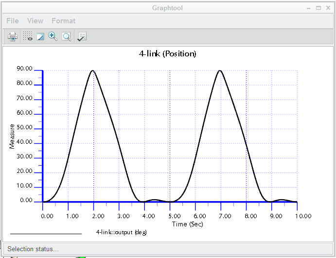
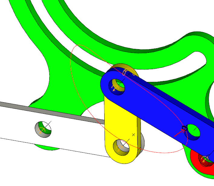
This is a 4-link mechanism that changes the rotation to a full 90 degree mechanism. Just to make it fun, I added the radial drag link profile.
The sketch in the part file has 2 "variables" that ensures the 90 degree "requirement".
These fix the length of the drive link and the radius of the fixed frame for the drag link.
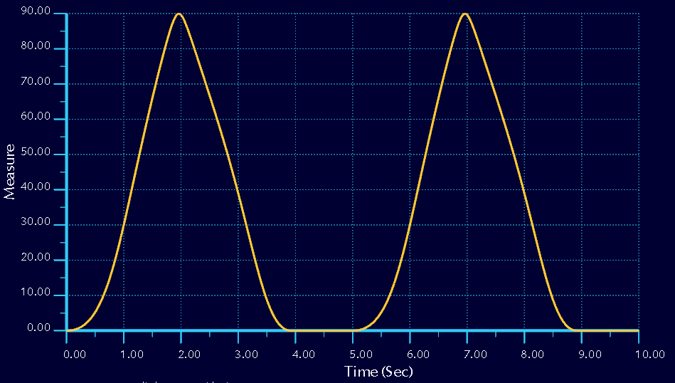
The output motion is captured with a measure feature. The data can be output to a text or excel file.
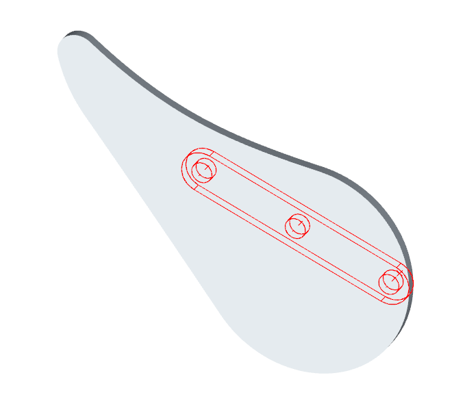
This is a trace-curve from an arbitrary vertex...
And a motion envelope creates a separate file. This is a single link at the high resolution setting (multi-body is default).
Since the "skeleton" is in the original file, family tables were used to make all the elements.
This allows the entire mechanism to be made with 1 part file and 1 assembly file.
Creo 3.0 attached.
Feb 07, 2015
06:39 PM
- Mark as New
- Bookmark
- Subscribe
- Mute
- Subscribe to RSS Feed
- Permalink
- Notify Moderator
Feb 07, 2015
06:39 PM
In a typical 4 link mechanism there are 3 moving parts and 1 ground part. In this, the ground part is merged with the slot, much like a slider-crank. Counting all the pieces makes this a 6 link mechanism.
While the same conversion can be done with a 4 link mechanism, this looks to offer the chance to alter the accelerations of the output in interesting ways.
Feb 07, 2015
07:14 PM
- Mark as New
- Bookmark
- Subscribe
- Mute
- Subscribe to RSS Feed
- Permalink
- Notify Moderator
Feb 07, 2015
07:14 PM
 okay, it was just a fun thing to create regardless of it's designation.
The idea was more to let sketches drive the geometry to achieve a result.
The same technique can be used to obtain specific outputs at specific time intervals by replacing the arc with a curve through points.
Obtaining the 0-degree dwell at the small bumps is easy to achieve by adding an r40 reverse radius at the vertical instance.
Feb 07, 2015
09:03 PM
- Mark as New
- Bookmark
- Subscribe
- Mute
- Subscribe to RSS Feed
- Permalink
- Notify Moderator
Feb 07, 2015
09:03 PM
Here I added a true dwell using the "skeleton" data (1st sketch) to create the slot in the extrusion feature.
Notice the ends of the slot are concentric with the ends of the stroke as well.
Feb 08, 2015
06:38 PM
- Mark as New
- Bookmark
- Subscribe
- Mute
- Subscribe to RSS Feed
- Permalink
- Notify Moderator
Feb 08, 2015
06:38 PM
Feb 7
Wow! I am impressed by the replies to my post (pardon my idiot typo in the title). I would like to find a way to activate Creo Elements Express version 6 on a non-internet-connected machine. I expect to spend many, many hours on learning the software, even with my AutoCAD background, and, regardless of what I do, my Web browsing machine just gets slower, and slower, and slower. Also, I want the highest possible security for some of my work, which could lead to patent applications. I wish to try the free version first, of course, to see how well I can make it work, but graduating to a purchased, professional level package is not out of the question.
I need to synthesize eight and ten bar linkages for some quite complicated input-output relations, in a machine design I'm working on. I have had some success with trial and error, but it takes a very long time to get things right, even with the assistance of the Hrones and Nelson atlas for fourbar sub-elements. It can get either quite frustrating or, um, "intriguing," depending on my mood.
I think it will be worthwhile for me to learn a parametric CAD program, and work out Kinzel and coathors' techniques, since I anticipate a lot of tough linkage design problems in the future.
Thank you!
Feb 08, 2015
07:03 PM
- Mark as New
- Bookmark
- Subscribe
- Mute
- Subscribe to RSS Feed
- Permalink
- Notify Moderator
Feb 08, 2015
07:03 PM
I'm glad you find this enjoyable. We tend to get a little "into it" sometimes.
Creo Elements Express is a different animal. It has some intuitive mechanism capabilities but overall, it is not "Pro|E"... it is CoCreate repackaged into the Creo family. I am not sure where to refer you to get more information on what you can and cannot do with Creo Elements, or the Express version.
You can get Creo Parametric for a 30 day trial. You want to be sure you have a good machine that is compatible before you start the license. A lot of things can go wrong in this regard. Feel free to ask here what may or may not work.
I think the free Elements Express has to be network connected. It is doing some kind of handshake with PTC that I can tell (feedback about software performance or something). Tech support may be able to clarify this.
I know I can run my fully licensed Creo without being net-connected. I fully appreciate your reservations here. It only needs a network card for its ID to license the software.
Seriously, if you are affiliated with an academic program, you definitely want to check out the academic options. Think of it as an extended trial for a minimal investment. Otherwise, it is a hard pill to swallow twice... the initial cost and the yearly maintenance. For what you describe, you will very likely need the mechanism dynamics extension.
For what you are wanting to do, there will be a steep learning curve. However, if you stick with this in a dedicated focus, it will broaden your knowledge very quickly. Even with the linkage above, with a pretty good understanding of Creo, it took me awhile to get it all smooth. Changes too can blow everything up and you have to backtrack to recover. I simply cannot thank the knowledgeable people here enough to get the insights I needed to get to the level I am now. And I've been at it for 4 years on a great variety of challenges. Prior to this period, I did use Pro|E for production work in design and detailing, but never even scratched the surface of these other capabilities.
Anyway, welcome again to the forum, John. Let us know what else we can help you with.
Feb 08, 2015
10:11 PM
- Mark as New
- Bookmark
- Subscribe
- Mute
- Subscribe to RSS Feed
- Permalink
- Notify Moderator
Feb 08, 2015
10:11 PM
Feb 8
Again, thanks. I, too, like to get "into it" sometimes. I guess that some of us engineers and inventors are "just born that way"
I will try out Creo Parametric for 30 days, but first, I'll find a third party book on the topic, and study up. I might also (blasphemy!) consider an alternative to PTC. One product retails for $199.00, and after all, "business is business."
Slightly off topic, let me here sing the praises of X-numbers, a free, downloadable add-on for Excel which allows arbitrary precision arithmetic to be used, seamlessly, within an Excel spreadsheet.
I do linkage analysis with Excel, setting up a spreadsheet with, say, 720 rows, each for a half degree of an input crank rotation, and then working through the trigonometric formulas, column by column. It beats writing code, and Excel lets me graph results in an almost hassle free way. Sometimes, though, Excel's native 15 decimal places of precision aren't enough, especially when finding deriviatives of complicated position versus crank angle results by the "lazy man's" method of just setting up finite difference expressions. I set up X-numbers to give me 60 decimal places of precision, and then, as a trial, compared accelerations around a circle done with finite differences against the simple omega squared times R formula. Thel largest devation was by a ratio of 0.999975. This seems good enough!
X-numbers comes in 2 versions, one for 2007 and later Excel versions, the other for pre-2007. Both are reasonably fast, on a by-now-ubiquituous Pentium 4 or later, 2.7 Ghz or up. Enjoy!
Feb 08, 2015
10:44 PM
- Mark as New
- Bookmark
- Subscribe
- Mute
- Subscribe to RSS Feed
- Permalink
- Notify Moderator
Feb 08, 2015
10:44 PM
That says a lot about your requirements and I for one will warn you that PTC has a real bad habit of calling certain calculations "good enough" when they barely reach single precision. For instance, numbers like 1/3 can be stored to 12 places total and rounds after than. Doing gears with odd ratios are rounded to almost unacceptable values (they said they'd work on that). In general, higher precision is the kind of stuff the Mathcad community does.
I have found all too often that curve equations are inextricably tied to the model accuracy where the starting angle of an involute -begins- at 2-someodd degrees. Curves also cannot do sharp corners in continuous results. It is a fit-to-points algorithm with little control over the fit and a fairly course distribution of points to star with.
Having said that, you get a lot of chances to do geometry based modeling and analysis but the final analysis to the precision you are talking about will require another level of sophistication.
If I am understanding your level or requirement correctly, you might invite a PTC rep with an "expert" to give you a definitive reply. However, I have already been quite vocal on this front and have not found a sympathetic ear on the side of PTC.
Feb 09, 2015
10:49 PM
- Mark as New
- Bookmark
- Subscribe
- Mute
- Subscribe to RSS Feed
- Permalink
- Notify Moderator
Feb 09, 2015
10:49 PM
Feb 9
Actually, the high precision requirement just comes in when I am taking derivatives by the down-and-dirty method of just finding the difference in X and Y values between a point on an output curve and the preceeding point, determining the linear approximation to the curve slope at the point in question, and then converting the per-crank-degree result to a per-unit-time result for a given crank rotational speed. Repeating this process gives higher order derivatives. However, subtracting very close values loses a lot of decimal places with each operation, so taking second, and possibly third, derivatives by this method requires a whole lot of precision to start out with. The sixty decimal places I referred to is probably overkill even so, but it is so easy to get this level of precision with an arbitrary-precision algorithm that one might as well do so.
This simple, brute force method of getting derivatives for velocity, acceleration, and perhaps jerk, from a complicated linkage equation is mostly useful just for making sure that accelerations do not get out of hand, for example. It is also the method that I see referred to most often in textbooks on linkage analysis.
One could, alternatively, find the derivatives of each formula in a linkage calculation chain in analytic form, and then use the same passing of intermediate variables from the starting point, the crank pin X, Y position at a given angle, and proceed through the whole chain, i.e. use the same kind of process used to find the position points on the output curve in the first place. This more exact approach is, however, a lot more work, especially when an eight or ten bar linkage is under consideration.
For actual linkage synthesis from precision points, there will always be some error. This can be minimized by using more precision points and by Chebyshev spacing of the precision points, which latter I am still scratching my head over. But, as we all know, linkages will in general offer less precision than would cams, for example. On the other hand, linkages are simpler and more rugged than cams, and are better suited to situations where loads can get high, and can change direction.
In my actual, practical application, the design can tolerate some imprecision. I could seriously benefit from a semi-automated way to synthesize linkages that can approximate my desired output curve. I can always check the results by using Excel as an analysis tool, after the much more difficult job of synthesis has been done in a parametric CAD program.
Feb 09, 2015
11:34 PM
- Mark as New
- Bookmark
- Subscribe
- Mute
- Subscribe to RSS Feed
- Permalink
- Notify Moderator
Feb 09, 2015
11:34 PM
 Okay, you can come back into the clubhouse...
Feb 10, 2015
12:15 AM
- Mark as New
- Bookmark
- Subscribe
- Mute
- Subscribe to RSS Feed
- Permalink
- Notify Moderator
Feb 10, 2015
12:15 AM
Feb 9
Ahh, good. I
I misspoke in my last post, concerning taking derivatives. I meant to say that one finds, for the first time derivative, the values of delta X and delta Y, then linearizes their slopes with repsect to crank angle increment, and goes from there to delta X over delta time, and delta Y over delta time. Not delta Y over delta X, which is not useful in this contest. One wants velocities in the X and Y directions. Ditto for higher derivatives. My boo boo.
In any event, linkage analysis is just straight plug-and-chug, when all of the link lengths, internal angles, and so forth are specified. Automating it with a computer, e.g. uing Excel with X-numbers, just reduces the tedium.
Synthesis, starting from a desired input to output relation and from there finding dimensions of a linkage that will provide said relation, has always been the large, growling bear, especially when complicated curves, and more than four bars, are involved. Using a parametric CAD program to simplify this job could be a major boon. Internally, the program's solver probably uses a huge number of numerical iterations to reach an answer - the beauty of it is that the designer is spared having to do this himself.
I have said about as much as my present state of knowledge allows me to. I am looking for a good book on Creo Parametric, which I can study at my leisure, and be ready to make best use of a 30 day free trial.
Feb 10, 2015
12:36 AM
- Mark as New
- Bookmark
- Subscribe
- Mute
- Subscribe to RSS Feed
- Permalink
- Notify Moderator
Feb 10, 2015
12:36 AM
Creo has been optimized for efficiency for the average user. It is controllable to some degree but not everyone in development got the memo that a few of us want real precision. Certainly in the 21st century a double precision database is no big deal... but it turns out to be so. CAD is about productivity, not science experiments.
Needless the say, you cannot make much beyond a few micron (yes, micro-meters!) in the real world which makes numbers to 12 places moot except in cases such as yours where cumulative error can create a real headache. Awareness will get you past a lot of it or point you to places where this counts.
For me, the advantages with CAD is knowing you are in the ballpark when you make some assumptions. If my numbers and CAD are way off, then there is something wrong with my napkin efforts. That gives me something to backtrack.
Enjoy your study. Your projects sound like a lot of fun.
