
Turn on suggestions
Auto-suggest helps you quickly narrow down your search results by suggesting possible matches as you type.
Showing results for
Turn on suggestions
Auto-suggest helps you quickly narrow down your search results by suggesting possible matches as you type.
Showing results for
Community Tip - Learn all about PTC Community Badges. Engage with PTC and see how many you can earn! X
- Community
- Creo+ and Creo Parametric
- 3D Part & Assembly Design
- Re: Proper way to dimenion a rounded corner? (ASTM...
Options
- Subscribe to RSS Feed
- Mark Topic as New
- Mark Topic as Read
- Float this Topic for Current User
- Bookmark
- Subscribe
- Mute
- Printer Friendly Page
Proper way to dimenion a rounded corner? (ASTM Y14?)
Sep 04, 2015
09:07 AM
- Mark as New
- Bookmark
- Subscribe
- Mute
- Subscribe to RSS Feed
- Permalink
- Notify Moderator
Sep 04, 2015
09:07 AM
Proper way to dimenion a rounded corner? (ASTM Y14?)
I'm having an argument with a vendor who made my part incorrectly. I do not know the ASTM code very well so I'm seeking advice. What is the proper way to dimension the part below? I've obviously chosen to dimension to the radius point and not the theoretical sharp. Is there ASTM code that covers this? I also sent the model to the vendor but he's saying I've dimensioned it wrong in the drawing and that's what he went by.

This thread is inactive and closed by the PTC Community Management Team. If you would like to provide a reply and re-open this thread, please notify the moderator and reference the thread. You may also use "Start a topic" button to ask a new question. Please be sure to include what version of the PTC product you are using so another community member knowledgeable about your version may be able to assist.
Labels:
- Labels:
-
2D Drawing
24 REPLIES 24
Sep 04, 2015
09:25 AM
- Mark as New
- Bookmark
- Subscribe
- Mute
- Subscribe to RSS Feed
- Permalink
- Notify Moderator
Sep 04, 2015
09:25 AM
I don't know about ASTM, but it seems pretty straight forward. The dimension doesn't say "to apex" or "to theoretical point", so if you put a set of calipers on it and it doesn't measure 30, it's not to print and made wrong.
Sep 04, 2015
09:29 AM
- Mark as New
- Bookmark
- Subscribe
- Mute
- Subscribe to RSS Feed
- Permalink
- Notify Moderator
Sep 04, 2015
09:29 AM
Thanx Tom. I dimensioned it like that EXACTLY for that purpose. Its impossible to measure to a theoretical sharp. The issue is my vendor is saying its improperly dimensioned. If someone knows the code and can quote it for me, that would allow me to settle the case.
Sep 04, 2015
09:46 AM
- Mark as New
- Bookmark
- Subscribe
- Mute
- Subscribe to RSS Feed
- Permalink
- Notify Moderator
Sep 04, 2015
09:46 AM
One question, does your print explicitly state that you dimension everything in accordance with ASTM Y14? If not, then he can't hold you to it. If so, then have him prove in the standard where what you did is wrong.
Sep 04, 2015
09:50 AM
- Mark as New
- Bookmark
- Subscribe
- Mute
- Subscribe to RSS Feed
- Permalink
- Notify Moderator
Sep 04, 2015
09:50 AM
no it does not. He simply states that it's supposed to be a different way. I just wanted to back my answer up with a standard if possible.
Sep 04, 2015
09:51 AM
- Mark as New
- Bookmark
- Subscribe
- Mute
- Subscribe to RSS Feed
- Permalink
- Notify Moderator
Sep 04, 2015
09:51 AM
I don't know about ASTM either. But I would have checked the model, checked the 2D (if available) or question it. I have seen detail like that where some people do it one way, some the other with no other note. So that being said, if I was handing that print out, I would either add a note of where the dimension is taken or possibly add a reference dimension to the sharps and note it theoretical sharp corner (TSC). I kind of throw standards out and assume the person reading the print needs as much help as possible to make my product correctly.
And on top of all that, just looking at the picture above, (and not seeing a tolerance block), I would assume either way would be in tolerance as the number is 30, and not 30.0 or 30.00.
Sep 04, 2015
09:37 AM
- Mark as New
- Bookmark
- Subscribe
- Mute
- Subscribe to RSS Feed
- Permalink
- Notify Moderator
Sep 04, 2015
09:37 AM
I do not see a detailed explanation of "theoretical corners" or "theoretical sharps" in my copy of Y14. Although there are some sections that state when a dimension is applied to intersecting surfaces, "crossing extension lines" should be used (sections 1.7.2, 1.7.2.1, 1.7.2.2). I would challenge your vendor to provide a copy of his standards, maybe we can all learn something.
Nevertheless, your design intent is what needs to be conveyed. I would interpret your drawing to indicate that it is diameter 30 on the outer radius surface itself, not the "theoretical" sharp. In my practice, if I ever provide a "theoretical" dimension, I would add that statement to the dimension or feature. Also, show a scaled-up detail view whenever important features like this can be misinterpreted. Good luck.
Sep 04, 2015
09:41 AM
- Mark as New
- Bookmark
- Subscribe
- Mute
- Subscribe to RSS Feed
- Permalink
- Notify Moderator
Sep 04, 2015
09:41 AM
Thanx Jeff. That is actually a good idea. I will see if I can get him to provide the standard. I too will always add a note if dimensions are not to actual geometry.
Sep 04, 2015
09:44 AM
- Mark as New
- Bookmark
- Subscribe
- Mute
- Subscribe to RSS Feed
- Permalink
- Notify Moderator
Sep 04, 2015
09:44 AM
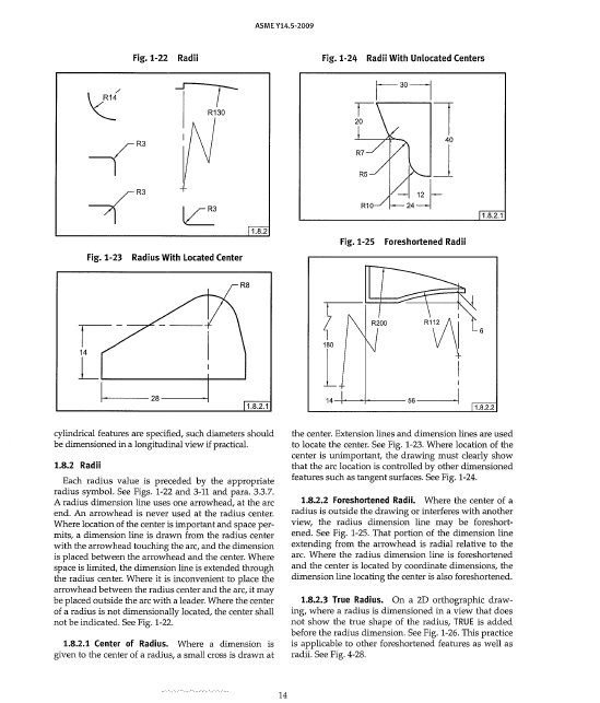
I've attached a scan of the page from Y14, glad to help a fellow grunt. 
Sep 04, 2015
09:47 AM
- Mark as New
- Bookmark
- Subscribe
- Mute
- Subscribe to RSS Feed
- Permalink
- Notify Moderator
Sep 04, 2015
09:47 AM
...but he didn't use points, so does that apply?
Sep 04, 2015
09:51 AM
- Mark as New
- Bookmark
- Subscribe
- Mute
- Subscribe to RSS Feed
- Permalink
- Notify Moderator
Sep 04, 2015
09:51 AM
I would say that if the feature was intended to be to the "sharps" as the vendor interpreted, then the drawing would in fact NEED those intersecting points. Therefore the drawing is without the points, and then the vendor is the one that got it wrong. ??
Sep 04, 2015
09:53 AM
- Mark as New
- Bookmark
- Subscribe
- Mute
- Subscribe to RSS Feed
- Permalink
- Notify Moderator
Sep 04, 2015
09:53 AM
I would agree. Let's call it the Jeff & Tom standard. 
Sep 04, 2015
09:56 AM
- Mark as New
- Bookmark
- Subscribe
- Mute
- Subscribe to RSS Feed
- Permalink
- Notify Moderator
Sep 04, 2015
09:56 AM
Well said! Now, about those consultation fees.....
Sep 04, 2015
09:40 AM
- Mark as New
- Bookmark
- Subscribe
- Mute
- Subscribe to RSS Feed
- Permalink
- Notify Moderator
Sep 04, 2015
09:40 AM
Anthony,
ASME Y14.5 Dimensioning and Tolerancing does not dictate how one should dimension a part but the language of dimensioning.
It is up to the user to determine the need and constraints for dimensioning of features and to be clear and concise without interpretation.
If you use solid models to build, follow ASME Y14.41 Digital Product Definition and Data Practices (as you mentioned you sent the model), but this also need to be defined.
Not knowing what the issue is, what you have provided seems proper to begin with but there is missing information and "grammatical" errors.
Can you provide more information as to the why the part was made incorrectly?
Ron
Sep 04, 2015
09:46 AM
- Mark as New
- Bookmark
- Subscribe
- Mute
- Subscribe to RSS Feed
- Permalink
- Notify Moderator
Sep 04, 2015
09:46 AM
When asked why the part was made improperly this was the response:
____________________________________________________________
If they wanted a .020 radius at that point they should have defined that
center location of the .020 radius, so you have the correct 30 deg location.
That would have defined the 1.181dia correct.
The angle and the .020 radius is defined correct with the given information
on the print.
Yes I can rework and adjust my CAD to get the .020 radius in the location
they want.
____________________________________________________________
If you ask me, he doesn't really have a clue, but he wants me to pay the tooling charge to change the mold. I have asked him if he interpreted the drawing the way he states in his response. If he did, then the part would have been BIGGER not smaller.
Sep 04, 2015
09:49 AM
- Mark as New
- Bookmark
- Subscribe
- Mute
- Subscribe to RSS Feed
- Permalink
- Notify Moderator
Sep 04, 2015
09:49 AM
Huh? The .02 radius is continuous from the vertical line to the angle line...
Sep 04, 2015
09:58 AM
- Mark as New
- Bookmark
- Subscribe
- Mute
- Subscribe to RSS Feed
- Permalink
- Notify Moderator
Sep 04, 2015
09:58 AM
He made a mold from a CAD file he made from your drawing instead of just using the CAD file you provided? Why in the world would he do that? We have this note that we typically use on all drawings for molded parts to make it clear to use our 3D CAD data, not the drawing:
THIS PART WAS DEVELOPED AS A SOLID CAD MODEL.
ALL TOOLING AND PROCESSING DEVELOPMENT SHOULD BE
BASED ON THE CAD DATA. DIMENSIONS ON THIS DRAWING
ARE FOR QUALITY CONTROL.
TWO AND THREE-DIMENSIONAL DATABASES ARE AVAILABLE.
CONTACT DESIGN CENTRAL ENGINEERING AT 614.890.0202
TO RECEIVE DATABASES.
Your drawing is clear, 30mm at the largest point which would be the OD of the 0.5mm radius (assuming this is round). You never indicated to sharp or to intersect, he assumed it. That's on him in my book.
Sep 04, 2015
10:11 AM
- Mark as New
- Bookmark
- Subscribe
- Mute
- Subscribe to RSS Feed
- Permalink
- Notify Moderator
Sep 04, 2015
10:11 AM
That's funny Doug. That's the first thing I asked. WTH would you redraw it if I sent you a model. I think I'm going to add that note to my drawings.
Sep 04, 2015
11:08 AM
- Mark as New
- Bookmark
- Subscribe
- Mute
- Subscribe to RSS Feed
- Permalink
- Notify Moderator
Sep 04, 2015
11:08 AM
Anthony,
This was the ASME y14.41 standard I mentioned earlier and I suggest you take a look at it.
No disrespect to Doug but his note does not cover all that is required.
I would suggest some notation to electronic rounding like:
DIGITAL MODEL IS CONSIDERED MASTER
ROUNDING OF DIMENSIONS SHALL BE IN ACCORDANCE WITH IEEE/ASTM S110
I would also suggest some notation to tolerancing, such as:
ALL SURFACES [ <profile of surface> | <numeric value> | <datum references> ] -> this is a GD&T Box
Please read more about this standard if you are choosing to use MBD concepts before just slapping notes on your drawing.
Ron
Sep 04, 2015
11:35 AM
- Mark as New
- Bookmark
- Subscribe
- Mute
- Subscribe to RSS Feed
- Permalink
- Notify Moderator
Sep 04, 2015
11:35 AM
Thanx Ron. I will look into that.
Sep 04, 2015
01:31 PM
- Mark as New
- Bookmark
- Subscribe
- Mute
- Subscribe to RSS Feed
- Permalink
- Notify Moderator
Sep 04, 2015
01:31 PM
Ron St.Pierre wrote:
No disrespect to Doug but ...
None taken, this note covers our needs and has served us well. I think it dates back some time, probably 15 years or more. I can certainly see the value in noting how rounding would be handled, we simply haven't found it to be an issue.
Sometimes we are superseded by the client's standards, one in particular has this very simple statement in their standard notes:
3. CREATE PART FROM 3D DATA PROVIDED BY [CLIENT].
That's a bit too casual for me, but that's how they handle it.
Sep 04, 2015
10:00 AM
- Mark as New
- Bookmark
- Subscribe
- Mute
- Subscribe to RSS Feed
- Permalink
- Notify Moderator
Sep 04, 2015
10:00 AM
Here is the page from the book....
Sep 04, 2015
11:53 AM
- Mark as New
- Bookmark
- Subscribe
- Mute
- Subscribe to RSS Feed
- Permalink
- Notify Moderator
Sep 04, 2015
11:53 AM
So all this said, I feel I can make the statement that the drawing is clearly and sufficiently dimensioned per ASME Y14. Would anyone disagree?
Also, I got this response from the vendor...
The 30mm diameter was drawn from the 34.2 dimension then the 30 deg angle was struck at that dia then the .5 radi was drawn.
In the upper right view you are showing the 30 degree angle is defined by the 30mm diameter.
That is standard engineering practice for definition of an angle on a diameter.
They clearly used the 30mm dim as the sharp point. But he later suggested that I should have done this instead...
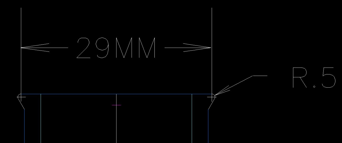
Either way, I did NOT add any extension lines or centerlines so he should have properly interpreted my drawing.
Sep 04, 2015
12:19 PM
- Mark as New
- Bookmark
- Subscribe
- Mute
- Subscribe to RSS Feed
- Permalink
- Notify Moderator
Sep 04, 2015
12:19 PM
That is standard engineering practice for definition of an angle on a diameter.
Maybe for them. It's only universal if actually written in a universal standard somewhere.
Sep 05, 2015
01:59 PM
- Mark as New
- Bookmark
- Subscribe
- Mute
- Subscribe to RSS Feed
- Permalink
- Notify Moderator
Sep 05, 2015
01:59 PM
The part was made using an assumption that was not factual or supported by the submitted drawing.
All "proper" interpretations are already covered. In this case, I too would have put a clarifying view on the drawing or a reference dimension of the smaller diameter.
The vendor is right in that rounds are typically calculated later and are not a critical element. In design, this is very poor control of the angled surface if its position on the diameter is indeed a design element where the overall OD is not as significant. Variation of that angled face will vary significantly if the radius tolerance is even 20% of 0.5mm. Not knowing the design intent, it is difficult to know what the "right" way to define this really is.
In the end, I find that these kind of arguments fall under the heading of "partnership agreements". If you value this supplier, you have purchasing strike a deal and chalk it up to experience. If this is a one off and you really don't expect future business with this supplier, you can push it harder, again, through the purchasing department. In the end, none of us will end up in court having to defend the right way to interpret ASME Y14.5 or ASME Y14.41. It really comes down to politics.
My opinion, the vendor should have confirmed and should fix the part. Since this is a tool-safe error anyway, it really is a reasonable consideration to tweak the mold along with whatever other changes may be beneficial. A shared cost if you gain added benefits would be a reasonable compromise. Politics is rarely an engineer's strong suit. Just agree to make your design intent clearer in the future and leave it at that.
