
Turn on suggestions
Auto-suggest helps you quickly narrow down your search results by suggesting possible matches as you type.
Showing results for
Turn on suggestions
Auto-suggest helps you quickly narrow down your search results by suggesting possible matches as you type.
Showing results for
Community Tip - Your Friends List is a way to easily have access to the community members that you interact with the most! X
- Community
- Creo+ and Creo Parametric
- 3D Part & Assembly Design
- Sketcher Dimension Location in Creo 2.0
Options
- Subscribe to RSS Feed
- Mark Topic as New
- Mark Topic as Read
- Float this Topic for Current User
- Bookmark
- Subscribe
- Mute
- Printer Friendly Page
Sketcher Dimension Location in Creo 2.0
Aug 01, 2014
08:00 AM
- Mark as New
- Bookmark
- Subscribe
- Mute
- Subscribe to RSS Feed
- Permalink
- Notify Moderator
Aug 01, 2014
08:00 AM
Sketcher Dimension Location in Creo 2.0
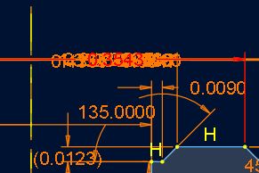
I tend to have to make a lot of complicated sketches in Creo. Does anyone know if there's a config setting to lock the dimension placement within a sketch so all the dimensions do not pile on top of each other as shown...
Thanks
Matt
This thread is inactive and closed by the PTC Community Management Team. If you would like to provide a reply and re-open this thread, please notify the moderator and reference the thread. You may also use "Start a topic" button to ask a new question. Please be sure to include what version of the PTC product you are using so another community member knowledgeable about your version may be able to assist.
Labels:
- Labels:
-
2D Drawing
- Tags:
- creo
- parametric
10 REPLIES 10
Aug 01, 2014
01:26 PM
- Mark as New
- Bookmark
- Subscribe
- Mute
- Subscribe to RSS Feed
- Permalink
- Notify Moderator
Aug 01, 2014
01:26 PM
This really needs an idea for a button in sketcher to offset dims. Developers have gotten really messy with their readability and clarity of sketches.
My peeve is with the leaders... why can they break a linear dim leader but not for angles?
And why do perimeter dims drop a half mile outside the frame fo the part? And why do angle dims zoom exponentially when normal dims don't? Seriously... it use to be better!
Aug 01, 2014
01:28 PM
- Mark as New
- Bookmark
- Subscribe
- Mute
- Subscribe to RSS Feed
- Permalink
- Notify Moderator
Aug 01, 2014
01:28 PM
What version are you using? You must be showing annotation, which I don't think has much to do with how they are placed in sketcher.
Aug 01, 2014
01:58 PM
- Mark as New
- Bookmark
- Subscribe
- Mute
- Subscribe to RSS Feed
- Permalink
- Notify Moderator
Aug 01, 2014
01:58 PM
Antonius,
I'm using Creo Parametric 2.0. I don't know what you mean by "showing annotation" other than within a drawing. The screenshot is of a sketch of a revolution. I do show constraints in my sketches if that's what you mean.
One would think that if you move dimensions around in a sketch, that they would stay there. Mine tend to move around. The sketch in the screenshot has at least twenty diameter dimensions in it. I didn't pile them on top of each other, Creo did. It gets old having to move ten different dimensions in order to pick the one you want.
It would be really nice if you could highlight a dimension by picking a leader.
I'd like to think that the most crucial part of the software would be pretty much perfected in 20 years.
Matt
Aug 01, 2014
02:28 PM
- Mark as New
- Bookmark
- Subscribe
- Mute
- Subscribe to RSS Feed
- Permalink
- Notify Moderator
Aug 01, 2014
02:28 PM
Interesting Matt. Somehow your sketch attributes are different than mine. For instance, the open leader on the 135 degree dim, and the line weight of the dimensions. I am on Creo 2 also, and it is certainly different.
I don't think I have ever had all those diameters stack up except when they are 1st generated by the intent manager. once I move them, they pretty much stay moved but still dependent on zoom states.
Aug 01, 2014
02:35 PM
- Mark as New
- Bookmark
- Subscribe
- Mute
- Subscribe to RSS Feed
- Permalink
- Notify Moderator
Aug 01, 2014
02:35 PM
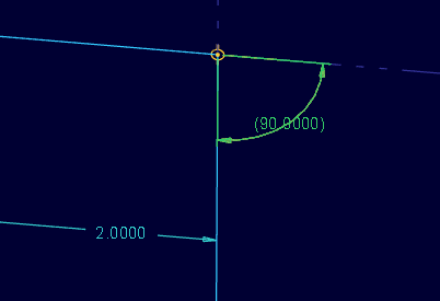
Okay, this is freaky! Now my angle dims -do- have a gap around the text!
You can see by my earlier image, this is -not- the norm for me.
Aug 01, 2014
03:34 PM
- Mark as New
- Bookmark
- Subscribe
- Mute
- Subscribe to RSS Feed
- Permalink
- Notify Moderator
Aug 01, 2014
03:34 PM
I'm going to have to pay closer attention to when it happens. It is definately weird.
Aug 01, 2014
03:57 PM
- Mark as New
- Bookmark
- Subscribe
- Mute
- Subscribe to RSS Feed
- Permalink
- Notify Moderator
Aug 01, 2014
03:57 PM
Never mind, it only shows the gap when you activate the "sketch view" so the sketch is normal to the screen.
Linear dimensions and diameter dimensions maintain their gap while angle dimensions don't.
This is worth reporting to CS  it annoys me terribly!
Aug 01, 2014
04:17 PM
- Mark as New
- Bookmark
- Subscribe
- Mute
- Subscribe to RSS Feed
- Permalink
- Notify Moderator

Aug 04, 2014
07:35 AM
- Mark as New
- Bookmark
- Subscribe
- Mute
- Subscribe to RSS Feed
- Permalink
- Notify Moderator
Aug 04, 2014
07:35 AM
Thanks. Thats 4 minutes 13 seconds I'll spend on chasing accuracy.
Aug 04, 2014
04:04 PM
- Mark as New
- Bookmark
- Subscribe
- Mute
- Subscribe to RSS Feed
- Permalink
- Notify Moderator
Aug 04, 2014
04:04 PM
Customer service assigned an SPR to the angle dimension behavior. I added the fact that this problem also existed in editing angular constraints (assemblies) or angle dimension in features (parts). Fixing it in one place should solve it in the others.
