
Turn on suggestions
Auto-suggest helps you quickly narrow down your search results by suggesting possible matches as you type.
Showing results for
Turn on suggestions
Auto-suggest helps you quickly narrow down your search results by suggesting possible matches as you type.
Showing results for
Community Tip - If community subscription notifications are filling up your inbox you can set up a daily digest and get all your notifications in a single email. X
- Community
- Creo+ and Creo Parametric
- 3D Part & Assembly Design
- Re: Two curve for one object in drawing
Options
- Subscribe to RSS Feed
- Mark Topic as New
- Mark Topic as Read
- Float this Topic for Current User
- Bookmark
- Subscribe
- Mute
- Printer Friendly Page
Two curve for one object in drawing
May 07, 2011
05:50 AM
- Mark as New
- Bookmark
- Subscribe
- Mute
- Subscribe to RSS Feed
- Permalink
- Notify Moderator
May 07, 2011
05:50 AM
Two curve for one object in drawing
Hello!
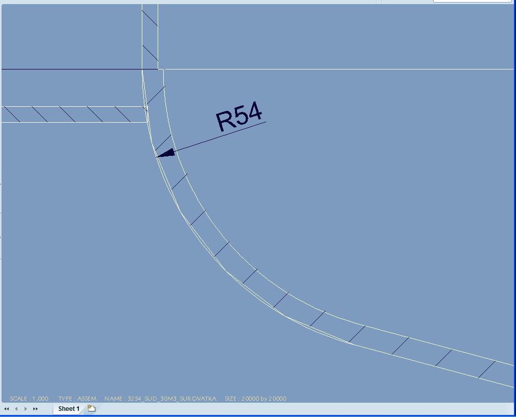
I created a part with revolved feature and a drawing. In section view of the part there are two curves for surface with radius. When I export the drawing to AutoCAD dwg format, these curves turn into spline and polyline and I have to delete one of them. How can I avoid this problem and have one curve only?
This thread is inactive and closed by the PTC Community Management Team. If you would like to provide a reply and re-open this thread, please notify the moderator and reference the thread. You may also use "Start a topic" button to ask a new question. Please be sure to include what version of the PTC product you are using so another community member knowledgeable about your version may be able to assist.
Labels:
- Labels:
-
2D Drawing
9 REPLIES 9
May 07, 2011
06:42 AM
- Mark as New
- Bookmark
- Subscribe
- Mute
- Subscribe to RSS Feed
- Permalink
- Notify Moderator
May 07, 2011
06:42 AM
hello
have you enabled hidden edge in this view ??
best regards
May 07, 2011
08:14 AM
- Mark as New
- Bookmark
- Subscribe
- Mute
- Subscribe to RSS Feed
- Permalink
- Notify Moderator
May 07, 2011
08:14 AM
I can't tell from the section view, but I suspect that the two "curves" represent real geometry. Is the surface drafted or angled? Is there both a solid surface and an independent surface feature? I'm betting on a geometric explanation. Could you show us a 3D view of the area in question?
David
May 07, 2011
08:16 AM
- Mark as New
- Bookmark
- Subscribe
- Mute
- Subscribe to RSS Feed
- Permalink
- Notify Moderator
May 07, 2011
08:16 AM
I also just noticed that the straight horizontal sectioned wall coming in from the left seems to have a solid end. Is this an assembly section?
May 07, 2011
01:30 PM
- Mark as New
- Bookmark
- Subscribe
- Mute
- Subscribe to RSS Feed
- Permalink
- Notify Moderator
May 07, 2011
01:30 PM
Hello David and Pierre,
I created this part only with revolve tool and thicken sketch in part mode - see pictures at my previous post Problem with thickness. and this one:
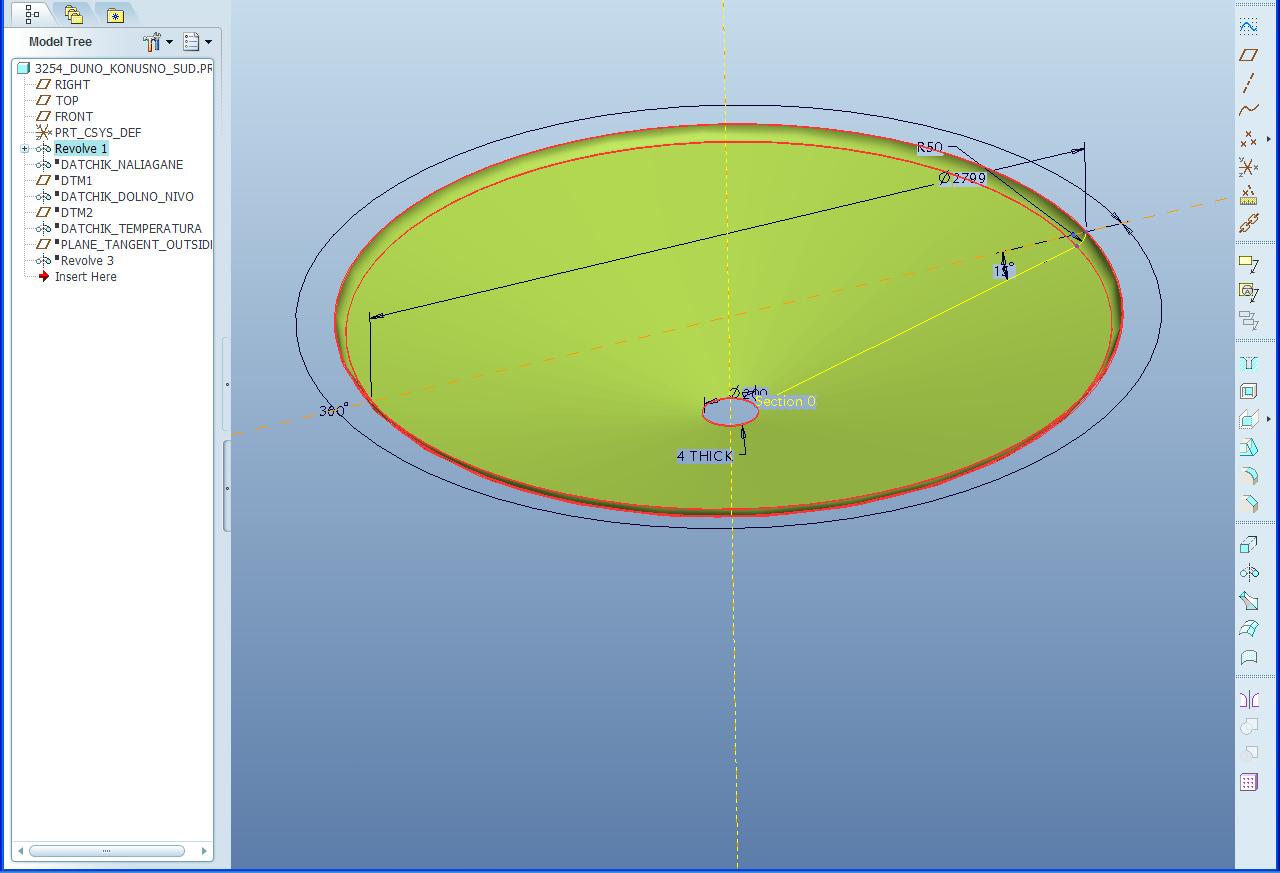
The model is with solid geometry only and there are no independent surfaces, I think.
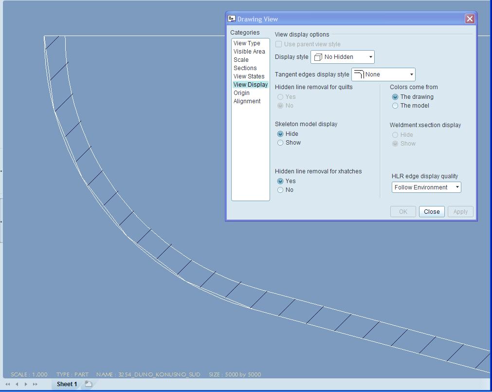
For view properties:
Indeed, at first I made assembly section but now I show part section and there is the same problem
May 08, 2011
02:42 PM
- Mark as New
- Bookmark
- Subscribe
- Mute
- Subscribe to RSS Feed
- Permalink
- Notify Moderator
May 08, 2011
02:42 PM
Well, I'm a bit mystified, but one question: are you sure that your section is right through the centerline of the revolve? If it's not, there will be two different curves, one at the section plane and one just slightly different profile curve of the "uncut" part.
May 08, 2011
03:48 PM
- Mark as New
- Bookmark
- Subscribe
- Mute
- Subscribe to RSS Feed
- Permalink
- Notify Moderator
May 08, 2011
03:48 PM
Yes, I am sure. My reference plane for sketch section and centerline is FRONT and for XSection in the drawing is the same.
May 08, 2011
03:24 PM
- Mark as New
- Bookmark
- Subscribe
- Mute
- Subscribe to RSS Feed
- Permalink
- Notify Moderator
May 08, 2011
03:24 PM
OK, scratch everything I've suggested so far. I just duplicated your problem, and think I've found the answer. Don't know exactly how it works, but I'm guessing that the "real" edge of the sectioned part has to be copied by the software to create a boundary edge for the section per se. They should look exactly the same. However, the aspect ratio you have in your model (thickness and radius to overall size) combined with the default way that curves are represented graphically (a series of small straight line segments) probably leads to this problem when each of the two versions of the curved edge is generated. Anyway, after duplicating your model and drawing, going to View/Display Settings/Edge/Line, and changing to Very High, the problem was solved.
May 08, 2011
04:10 PM
- Mark as New
- Bookmark
- Subscribe
- Mute
- Subscribe to RSS Feed
- Permalink
- Notify Moderator
May 08, 2011
04:10 PM
BUMP-ing this because my system shows my last comment and yours "crossing in the mail."
May 09, 2011
03:20 PM
- Mark as New
- Bookmark
- Subscribe
- Mute
- Subscribe to RSS Feed
- Permalink
- Notify Moderator
May 09, 2011
03:20 PM
Thank you!
