
Turn on suggestions
Auto-suggest helps you quickly narrow down your search results by suggesting possible matches as you type.
Showing results for
Turn on suggestions
Auto-suggest helps you quickly narrow down your search results by suggesting possible matches as you type.
Showing results for
Community Tip - Learn all about the Community Ranking System, a fun gamification element of the PTC Community. X
- Community
- Creo+ and Creo Parametric
- 3D Part & Assembly Design
- Use Simplified Rep in Relations
Options
- Subscribe to RSS Feed
- Mark Topic as New
- Mark Topic as Read
- Float this Topic for Current User
- Bookmark
- Subscribe
- Mute
- Printer Friendly Page
Use Simplified Rep in Relations
Feb 24, 2017
03:26 PM
- Mark as New
- Bookmark
- Subscribe
- Mute
- Subscribe to RSS Feed
- Permalink
- Notify Moderator
Feb 24, 2017
03:26 PM
Use Simplified Rep in Relations
Hi,
I have assembly of, let's say, 2 components, A and B. They are assembled at distance D and angle X with respect to each other. Now I want to create 3 different simplified Rep in my assembly, say 1, 2 and 3. My requirement is to change values of D and X with each Simplified Rep, I choose to have in my assembly to be active. i.e. For Simplified Rep 1,
Value of D=d1 and X=x1;
For Simplified Rep 2,
Value of D=d2 and X=x2;
For Simplified Rep 3,
Value of D=d3 and X=x3
I think, there should be some way to link simplified Rep name and dimension through relations, to change the dimension values with respective Simplified Rep. Or is there any other way around to achieve this without adding same component multiple times in assembly? Please help.
Thanks,
Bhavin
Labels:
- Labels:
-
2D Drawing
29 REPLIES 29
Feb 24, 2017
04:01 PM
- Mark as New
- Bookmark
- Subscribe
- Mute
- Subscribe to RSS Feed
- Permalink
- Notify Moderator
Feb 24, 2017
04:01 PM
Simplified reps are not designed for this purpose. Family tables are.
Feb 27, 2017
07:56 AM
- Mark as New
- Bookmark
- Subscribe
- Mute
- Subscribe to RSS Feed
- Permalink
- Notify Moderator
Feb 27, 2017
07:56 AM
But that will create additional CAD files in windchill (instances).
Feb 27, 2017
08:15 AM
- Mark as New
- Bookmark
- Subscribe
- Mute
- Subscribe to RSS Feed
- Permalink
- Notify Moderator
Feb 27, 2017
08:15 AM
Simplfied rep functionality is mostly for large assembly management. I have seen a few instance of use of them for controlling part/assembly configuration but it is not what the functionality was designed to do.
Just from what you are describing in your original post, have you looked in to flexible components in assembly mode?
Feb 27, 2017
10:49 AM
- Mark as New
- Bookmark
- Subscribe
- Mute
- Subscribe to RSS Feed
- Permalink
- Notify Moderator
Feb 27, 2017
10:49 AM
Flexible Components will not provide the ability to create several different selectable, easily retrievable configurations using the same two components. You can create the configurations well enough - but you sure can't retrieve them quickly. Plus, the more flexible components you add to an assembly, the slower the assembly becomes.
In other words, there's a performance hit for using too many flexible components. Therefore, I recommend using them for what they're intended for - showing a component in a slightly different state after it's been added to an upper-level assembly. I've used this many times:
- Displayed a battery holder with plastic latches which were supposed to flex and "snap" into place when placed into the next higher assembly. At rest, the latches are slack. When assembled, they are 'flexed' to show the installed/'snapped' configuration.
- Shock absorber shown uncompressed as an individual part but shown compressed when installed.
- Springs, coils, clamps, and other items which, when installed, are shown differently than "at rest"
I do not use Flexible Components for the use case described by the original poster but it all comes down to intent. There are several ways to achieve the goal - perhaps we need more data from the original poster before we can make a complete determination. From the information given, it's not clear what the purpose is. If I had to guess though, my first instinct would still be Mechanism Constraints.
Feb 27, 2017
11:00 AM
- Mark as New
- Bookmark
- Subscribe
- Mute
- Subscribe to RSS Feed
- Permalink
- Notify Moderator
Feb 27, 2017
11:00 AM
That's funny because the way I read the original post, I thought of a spring...
For instance, if the valve is closed, 'd1' is "0" and the spring is at 'x1' fully compressed dimension, if the valve is open, 'd2' is 1 and the spring "x2" is fully extended. And then everything in between is possible.
Definitely need a more precise description to get to an answer.
Feb 27, 2017
12:20 PM
- Mark as New
- Bookmark
- Subscribe
- Mute
- Subscribe to RSS Feed
- Permalink
- Notify Moderator
Feb 27, 2017
12:20 PM
Family tables create -no- additional CAD files. That's the whole point of family tables. No additional files. There is only one file.
It will create additional identifiable records in Windchill, all of which will point to the same file.
Feb 27, 2017
01:34 PM
- Mark as New
- Bookmark
- Subscribe
- Mute
- Subscribe to RSS Feed
- Permalink
- Notify Moderator
Feb 27, 2017
01:34 PM
To be fair, he did say "additional CAD files in Windchill (instances)" which is accurate.
The negligible size of an actual CAD file is not really a concern. Therefore, criticism of family tables isn't necessarily related to the presence of an actual CAD file. But, having instances which must be managed in Windchill, can be a concern. Many companies have moved away from "Assembly" family tables due to the complications arising from their maintenance.
We've been promised inheritance tools to mitigate some of these issues but they have no materialized. With each new version of Creo we're told it's coming in the "next rev".
Feb 27, 2017
02:39 PM
- Mark as New
- Bookmark
- Subscribe
- Mute
- Subscribe to RSS Feed
- Permalink
- Notify Moderator
Feb 27, 2017
02:39 PM
It's not accurate. Why contradict this? It just spreads the ignorance about how family tables work and how Windchill manages Part records.
Feb 27, 2017
02:47 PM
- Mark as New
- Bookmark
- Subscribe
- Mute
- Subscribe to RSS Feed
- Permalink
- Notify Moderator
Feb 27, 2017
02:47 PM
Family table is not an option in my case. Also, creating snapshots by Mechanism constraints will be A very difficult output for the receiver (in my case, customer), who has limited knowledge about Creo. That is why, I am looking to create simplified Rep, in which, with each simplified Rep, parts are assembled at different dimensions. That too without using same components multiple times at different dimension values. so as I mentioned in my question, we have assembly of 2 components, placed at certain dimension with respect to each other and we need their location to be changed with each simplified Rep in that assembly.
However, thanks a lot for your answers to my question.
Thanks,
Bhavin
Feb 27, 2017
03:00 PM
- Mark as New
- Bookmark
- Subscribe
- Mute
- Subscribe to RSS Feed
- Permalink
- Notify Moderator
Feb 27, 2017
03:00 PM
Hi Bhavin...
In that case, your options are (in order):
- Assemble Multiple Sets of Components and use Simplified Reps as you've already mentioned
- Family Tables as David mentioned - perhaps with Multiple Constraint Sets per Martin Hanak
I know I sound like a broken record here but... still... mechanism constraints is the way to go. You can publish these to Creo View. Even a customer with zero Creo knowledge can pick on Annotation Sets in Creo View and see your assembly in all 3 different configurations without extraneous components. If your customer's knowledge is so severely limited they cannot click on a link at the bottom of a page - or a picture of the model in the various states, you can help educate them within 3 or 4 powerpoint slides.
Unless you want a family table or several sets of components contained within your assembly Master Rep, there's no other option. You can still click dimensions and regenerate the way you always have - I'm not sure why mechanism constraints is less desirable than simp reps. Neither are something a very basic user tends to understand. Certainly neither concept is difficult, though.
Feb 27, 2017
02:54 PM
- Mark as New
- Bookmark
- Subscribe
- Mute
- Subscribe to RSS Feed
- Permalink
- Notify Moderator
Feb 27, 2017
02:54 PM
I guess I don't understand what you mean - no one is trying to start a disinformation campaign about family tables. Let's look at the facts, here...
ONE FILE controls the table - true.
That ONE FILE appears as numerous instances within Windchill - true.
Therefore, what the original posted said was true. With all due respect, I think you're parsing words and being more precise than the situation calls for. Instances are not separate files but they may as well be! Instances can exist at separate lifecycle states. Instances can exist at separate versions (revision + iteration). Therefore, to most users they appear to have most of the characteristics of a standalone file. Yet, because behind the scenes they are all contained within one "physical" file, there are numerous logistical issues with them.
Specifically, assembly family tables for design purposes are often (but not always) more trouble than they are worth. Family tables are excellent for library items - including small assemblies which may be a library item. To successfully use them, you must adopt a host of 'best practices' including rules like never delete an instance once it's been checked in and other various pains in the neck.
Most of the time when people use assembly family tables, they are doing so to simulate some kind of motion or alternate configurations. Maybe they want to show a door in the open AND closed positions on an electrical box. Or... perhaps they want to show a forklift with the "forks" both on the ground and lifted to their maximum extent in the air. These are not good uses for family tabled assemblies. Mechanism constraints and snapshots do this same job much more elegantly - and without ANY of the additional artifacts of family tables. No instances. No generics. No weird icons in Windchill. No separate wtParts. No potential for accidentally releasing or revising one instance without the others, etc. And, if you ever needed to delete an iteration, much less hassle to do so.
No one is a bigger supporter of family tables than I am - but they are not the cleanest construct offered by Creo and managing them within Windchill and the Workspace Browser can be a headache. There's no reason to intentionally inflict them on others unless there's a good reason.
I think the original poster was just commenting on the additional line items within Windchill (instances) which look and behave as standalone files. Technically, they are not... but I don't think that matters in regards to the question at hand.
Feb 27, 2017
04:43 PM
- Mark as New
- Bookmark
- Subscribe
- Mute
- Subscribe to RSS Feed
- Permalink
- Notify Moderator
Feb 27, 2017
04:43 PM
There is one file. What the original poster said was "additional CAD files" which is more than one. There aren't more than one. That is not accurate, even though you went out of your way to state that it was.
That's disinformation.
Sure, mechanism is just great. Has a few distinguishing things. Like it needs a Mechanism license for anyone who touches it in order to change it.
Feb 27, 2017
07:05 PM
- Mark as New
- Bookmark
- Subscribe
- Mute
- Subscribe to RSS Feed
- Permalink
- Notify Moderator
Feb 27, 2017
07:05 PM
We'll have to agree to disagree. Disinformation can hardly be claimed when I also went out of my way to acknowledge that there is, indeed, only one file.
I felt the original poster was making a general statement that he didn't wish to manage instances which he saw as "CAD files". I think the term was sufficiently vague that he expected us to understand what he meant. My assertion is that most people will see instances as separate files for that's how they behave. Technically, they are not - but that was not the poster's point. His point was he didn't want to manage them.
With very few exceptions, it literally behaves just like an independent file. Either way, it is a massive pain in the neck. Therefore, does it technically matter one way or the other? I think debating the technical precision of the argument doesn't solve the poster's dilemma. I was merely trying to address his concern in a way that didn't involve managing more than one object in Windchill.
Feb 28, 2017
01:09 AM
- Mark as New
- Bookmark
- Subscribe
- Mute
- Subscribe to RSS Feed
- Permalink
- Notify Moderator
Feb 28, 2017
01:09 AM
Flexible components are essentially "family tables" on the fly. Please take a look at this example and see if it fits your needs:
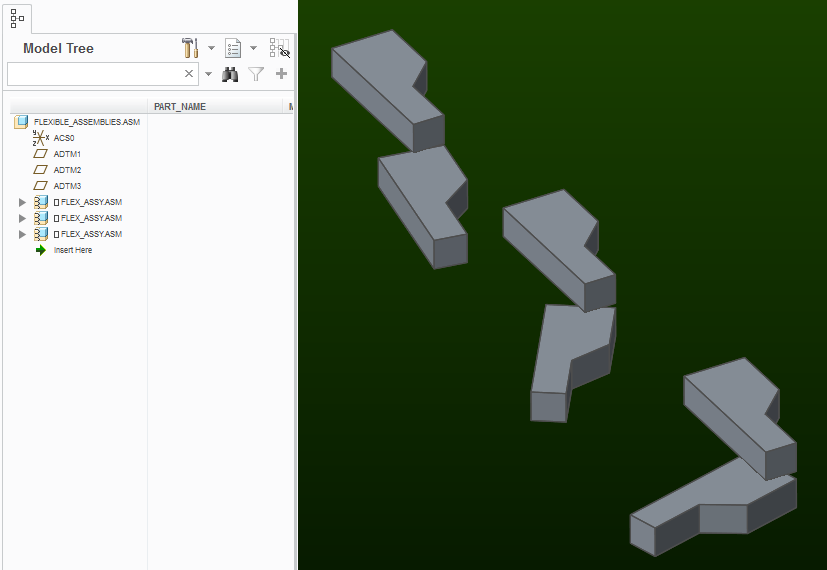
As others have already stated, your goal of linking an assembly configuration to a simplified representation is just not possible. Simplified reps control the state of the model tree, not of parameter or dimension values...
Feb 24, 2017
06:26 PM
- Mark as New
- Bookmark
- Subscribe
- Mute
- Subscribe to RSS Feed
- Permalink
- Notify Moderator
Feb 24, 2017
06:26 PM
Hi Bhavin...
Several things come to mind here:
- Family tables can perform this function as Dave Schenken mentioned
- Mechanisms with Snapshots can also perform this function
- Potentially flexible components (varying dimensions) can also do it.
- Simplified Reps with duplicate components can also be used (not recommended)
Your goal here should be to use mechanism constraints. Even if your model is not necessarily supposed to be a true mechanism, mechanism constraint which allow motion are your best friend here. But WHY?
With mechanism constraints, you can take Snapshots. This allows you to assemble ONE component A and ONE component B - but display them in various positions. You do not have to assemble multiple versions of the same components. Once you've assembled them, you can move them to the desired values of "D" and "X". Then you take a "Snapshot" and name it! You can recall any snapshot by simply double-clicking it from the list of saved snapshots.
You can take this further:
- Make Snapshots available in drawings. This allows you to show both configurations on the same drawing at the same time - without using duplicate components! No simp reps. No family tables. No hassles!
- Assign Snapshots to Combined States. Using combined states, you can add named tabs to the bottom of your screen. Maybe you name them "Position 1", "Position 2" and "Position 3". You can set the model into any given state by simply clicking the tab.
- Publish snapshots as combined states in Creo View. You can recall your combined states in Creo View (some publishing settings are required). If you have the Animation license for Creo View, you can make quick animations from these snapshots.
The benefits of Mechanisms and Mechanism constraints goes farther than this - but hopefully you get the idea. Of course, this is assuming your license supports at least mechanism constraints (as opposed to standard assembly constraints).
Research this topic a bit on your own and give it a try - I think you'll find this gives you what you want without headaches.
Thanks!
-Brian
Feb 27, 2017
04:52 PM
- Mark as New
- Bookmark
- Subscribe
- Mute
- Subscribe to RSS Feed
- Permalink
- Notify Moderator
Feb 27, 2017
04:52 PM
Consider the use of Explode states. They can be combined with Simplified reps using Combined States to keep them coordinated.
Feb 27, 2017
06:53 PM
- Mark as New
- Bookmark
- Subscribe
- Mute
- Subscribe to RSS Feed
- Permalink
- Notify Moderator
Feb 27, 2017
06:53 PM
Agreed. And indeed, Snapshots saved within the Mechanism Drag window show up as "Explode States" within a drawing.
Feb 28, 2017
12:57 AM
- Mark as New
- Bookmark
- Subscribe
- Mute
- Subscribe to RSS Feed
- Permalink
- Notify Moderator
Feb 28, 2017
12:57 AM
I'm pretty sure one can assemble components using the standard "mechanism constraints" without the Mechanism Design extension. I started a session of with only the FoundationAdv license and no extensions. Mechanism Design didn't show up in the list of features. Yet the pin joints, sliders, etc were all available for assembling components.
And I think the most useful for this problem is the "Drag Components/Take Snapshots" tool. Without it, the generation of explode states using the view manager is very tedious.
Feb 28, 2017
07:26 AM
- Mark as New
- Bookmark
- Subscribe
- Mute
- Subscribe to RSS Feed
- Permalink
- Notify Moderator
Feb 28, 2017
07:26 AM
The Mechanism Design Extension (MDO) adds an entire 'subsystem' of commands used in conjunction with basic mechanism constraints. I've always been able to use Mechanism Constraints without the added license - although perhaps it comes along with the Advanced Assembly Extension (AAX) and I've just never noticed.
Someone like Martin Hanak probably has the full story on something like this - maybe he'll chime in.
Thanks!
-Brian
Feb 28, 2017
07:59 AM
- Mark as New
- Bookmark
- Subscribe
- Mute
- Subscribe to RSS Feed
- Permalink
- Notify Moderator
Feb 28, 2017
07:59 AM
Info:
Mechanism_Design (127) is included in almost all licenses, enables assembling using special constraint - Pin, Slider, Cylinder, ... and analyzing mechanism behavior
Mechanism_Dynamics (191) is available as addtitional software package, enables entering dynamic properties like static/kinematic friction and analyzing mechanism behavior
Mh
Martin Hanák
Feb 28, 2017
08:04 AM
- Mark as New
- Bookmark
- Subscribe
- Mute
- Subscribe to RSS Feed
- Permalink
- Notify Moderator
Feb 28, 2017
08:04 AM
By the way - I'm now patting myself on the back for knowing Martin was the right person to answer questions about licensing. He's a licensing encyclopedia! Thank you, Martin!

Feb 28, 2017
08:06 AM
- Mark as New
- Bookmark
- Subscribe
- Mute
- Subscribe to RSS Feed
- Permalink
- Notify Moderator
Feb 28, 2017
08:06 AM
Well, in our system, we have an old set of licenses that do not have either option. When I click on the "Mechanism" icon in the Motion group of the Applications tab in the ribbon, then the message "The option Mechanism_Design has not been acquired".
Still, the pin, slider, cylinder, are all available. So there's no excuse for using standard constraints when assembling components that are supposed to be moveable
Feb 28, 2017
08:13 AM
- Mark as New
- Bookmark
- Subscribe
- Mute
- Subscribe to RSS Feed
- Permalink
- Notify Moderator
Feb 28, 2017
08:13 AM
Agreed! Absolutely!
I think Martin is saying that Mechanism Design enables the pin, sliders, etc in regular Creo assembly mode. The Mechanism Dynamics license enables the Mechanism icon in the Applications tab and also turns on some other features. For example, I think you need Mechanism Dynamics to assign servo motors.
Either way, I think the point is - everyone should familiarize themselves with Mechanism Constraints if they're modeling any joint designed for motion. PTC hasn't really hammered this in their training. It should be standard to differentiate the two techniques and explain to new users the benefits and limitations of each constraint type. I find most people understand the regular constraints and have never bothered to see what fantastic benefits the mechanism constraints offer!
Feb 28, 2017
08:34 AM
- Mark as New
- Bookmark
- Subscribe
- Mute
- Subscribe to RSS Feed
- Permalink
- Notify Moderator
Feb 28, 2017
08:34 AM
Mechanism Design enables the pin, sliders, etc in regular Creo assembly mode. The Mechanism Dynamics license enables the Mechanism icon in the Applications tab and also turns on some other features. For example, I think you need Mechanism Dynamics to assign servo motors.
No, this is not correct. Mechanism design enable the mechanism icon and includes the ability to use gear, cams, 3D contact, servo motors, kinematic analysis, etc. It does NOT include the ability to do dynamic analysis (with gravity, mass, and forces) or to use springs.
Edit: See this: https://support.ptc.com/appserver/cs/view/solution.jsp?n=CS42033
Feb 28, 2017
08:36 AM
- Mark as New
- Bookmark
- Subscribe
- Mute
- Subscribe to RSS Feed
- Permalink
- Notify Moderator
Feb 28, 2017
08:36 AM
Thanks, Tom... I should have done more research before posting. Thanks for the correction.
Feb 28, 2017
08:18 AM
- Mark as New
- Bookmark
- Subscribe
- Mute
- Subscribe to RSS Feed
- Permalink
- Notify Moderator
Feb 28, 2017
08:18 AM
Note:
In old licenses (PROE_FoundationAdv), Mechanism_Design (127) is provided as separate INCREMENT in license file. Launch command must be properly configured to be sure that parametric.psf file contains following info:
ENV=CREOPMA_FEATURE_NAME=PROE_FoundationAdv (127)
MH
Martin Hanák
Feb 28, 2017
04:22 AM
- Mark as New
- Bookmark
- Subscribe
- Mute
- Subscribe to RSS Feed
- Permalink
- Notify Moderator
Feb 28, 2017
04:22 AM
How about controlling the position of the components with relations and then creating mapkeys to change the relations?
Mar 10, 2017
12:25 PM
- Mark as New
- Bookmark
- Subscribe
- Mute
- Subscribe to RSS Feed
- Permalink
- Notify Moderator
Mar 10, 2017
12:25 PM
you could use multiple constraint sets, then make the PTC_CONSTRAINT_SET flexible. You only need to assemble in one set of parts for this application.
Apr 17, 2017
12:13 AM
- Mark as New
- Bookmark
- Subscribe
- Mute
- Subscribe to RSS Feed
- Permalink
- Notify Moderator
Apr 17, 2017
12:13 AM
I suggest to create a Pro/Program.
With inputs like A, B, C.....
Upon regeneration if user selects input as A, then X and Y values are X1 and Y1,
If user selects B, then X and Y are X2 and Y2
and so on.........
