
Turn on suggestions
Auto-suggest helps you quickly narrow down your search results by suggesting possible matches as you type.
Showing results for
Turn on suggestions
Auto-suggest helps you quickly narrow down your search results by suggesting possible matches as you type.
Showing results for
Community Tip - You can change your system assigned username to something more personal in your community settings. X
- Community
- Creo+ and Creo Parametric
- 3D Part & Assembly Design
- drawing view scale
Options
- Subscribe to RSS Feed
- Mark Topic as New
- Mark Topic as Read
- Float this Topic for Current User
- Bookmark
- Subscribe
- Mute
- Printer Friendly Page
drawing view scale
Sep 05, 2012
11:57 AM
- Mark as New
- Bookmark
- Subscribe
- Mute
- Subscribe to RSS Feed
- Permalink
- Notify Moderator
Sep 05, 2012
11:57 AM
drawing view scale
Hello Everyone,
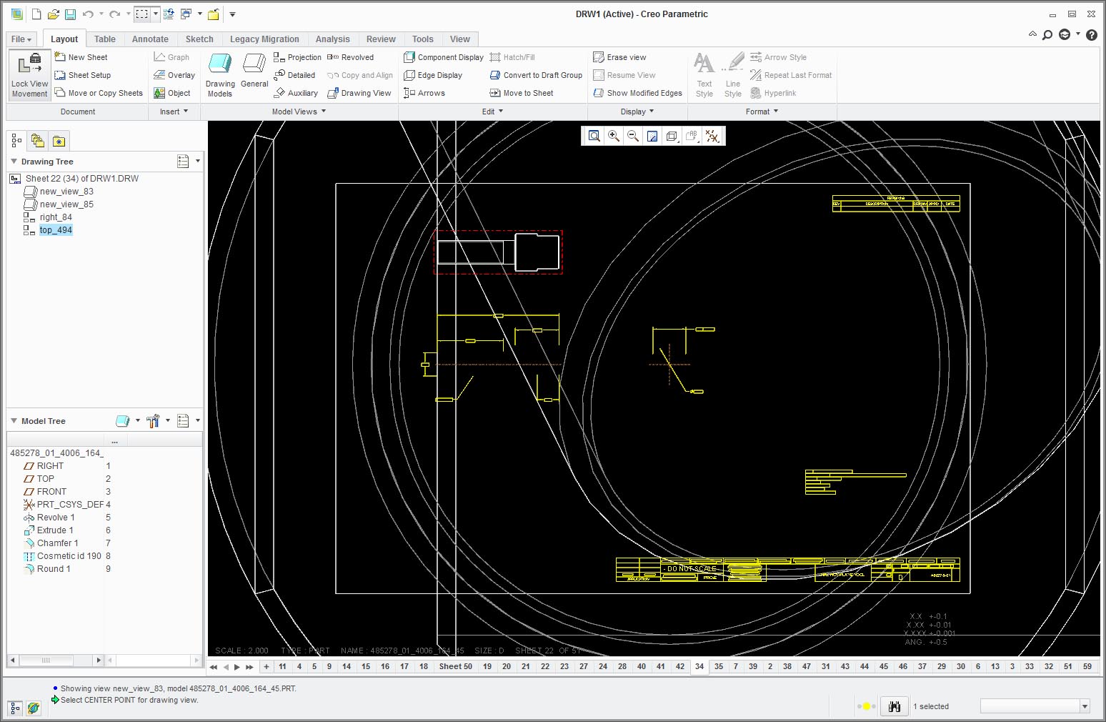
I've got a user with a multi-sheet drawing of an assembly (around 50 sheets). Most of the sheets detail individual parts of the assembly. On four of them, the piece part display is blown up so large that it's way larger than the drawing format. Each of the four sheets has a different part. However, the view scale and any measurement shows up correctly, and it prints correctly. If a new view is created, it shows up at the proper scale. Has anyone seen this, and how did you fix it without deleting all of the views on the sheet and starting over? Exiting and restarting Creo did not fix the issue. We are using Creo 2.0, M010.
Thanks,
Dave Clark
Sr. CAD Application Engineer
Dukane Corporation
Intelligent Assembly Solutions Division
2900 Dukane Drive
St. Charles, IL 60174
630-797-4922 (Phone)
630-797-4949 (Fax)
[cid:image001.png@01CD8B55.3D5C90D0][cid:image003.png@01CD8B55.3D5C90D0]<http: twitter.com=" dukaneias=">[cid:image004.png@01CD8B55.3D5C90D0]<http: www.youtube.com=" user=" dukaneultrasonics=">">http://usblog.dukane.com[cid:image002.png@01CD8B55.3D5C90D0]<http: www.facebook.com=" pages=" dukane-intelligent-assembly-solutions=" 3139592...
[cid:image005.jpg@01CD8B55.3D5C90D0]
This thread is inactive and closed by the PTC Community Management Team. If you would like to provide a reply and re-open this thread, please notify the moderator and reference the thread. You may also use "Start a topic" button to ask a new question. Please be sure to include what version of the PTC product you are using so another community member knowledgeable about your version may be able to assist.
Labels:
- Labels:
-
2D Drawing
8 REPLIES 8
Sep 05, 2012
02:02 PM
- Mark as New
- Bookmark
- Subscribe
- Mute
- Subscribe to RSS Feed
- Permalink
- Notify Moderator
Sep 05, 2012
02:02 PM
I should also note, this drawing package was working fine for a number of days. All of the sheets and views were displaying properly. We can't seem to determine what action may have caused the display to get out of scale on these four sheets, but at one time they were fine.
Thanks,
-Dave
Thanks,
-Dave
Sep 05, 2012
03:46 PM
- Mark as New
- Bookmark
- Subscribe
- Mute
- Subscribe to RSS Feed
- Permalink
- Notify Moderator
Sep 05, 2012
03:46 PM
I have recently run into something seeming to be a bug so see if this might be the problem...
When placing a view, I use combined states for two different views of a part, one flat pattern and one bent. For some reason, only one of the two views would follow the default scale. The other view had to be set using the properties/scale option.
I will also add that having 50 sheets to a drawing is very bold. If that file ever got corrupted, you would be in a world of hurt. I've already had drawing corruption using datum tag annotations. Be careful!
Sep 05, 2012
04:22 PM
- Mark as New
- Bookmark
- Subscribe
- Mute
- Subscribe to RSS Feed
- Permalink
- Notify Moderator
Sep 05, 2012
04:22 PM
I've attached some images that hopefully clarify what we're looking at. In the 01 image, this is the display when the sheet is viewed. In the 02 images, you can see a new view added and it's the correct scale (as was the other views when the sheet was created). In the 03 image, it's zoomed out so you can get the full effect.
I hope the image file sizes aren't too large.
Thanks,
-Dave
I hope the image file sizes aren't too large.
Thanks,
-Dave
Sep 05, 2012
04:39 PM
- Mark as New
- Bookmark
- Subscribe
- Mute
- Subscribe to RSS Feed
- Permalink
- Notify Moderator
Sep 05, 2012
04:39 PM
I wonder if that scale factor is exactly 25.4...
or 2(scale) x 25.4. Could it be that there is a SAE to SI issue somewhere in the model?
What date code and version are you using?
Can you submit this to PTC support for evaluation?
This is the kind of corruption I was refering to. If you redefine these views, will they remain stable of willthey again corrupt themselves?
Sep 05, 2012
04:44 PM
- Mark as New
- Bookmark
- Subscribe
- Mute
- Subscribe to RSS Feed
- Permalink
- Notify Moderator
Sep 05, 2012
04:44 PM
I'll have the user check out the file and see if there are unit conversion issues. The user is on Creo 2.0 M010, and I've opened the file using M020 to no avail.
Thanks,
-Dave
Thanks,
-Dave
Sep 05, 2012
04:56 PM
- Mark as New
- Bookmark
- Subscribe
- Mute
- Subscribe to RSS Feed
- Permalink
- Notify Moderator
Sep 05, 2012
04:56 PM
It is very important that these files find their way back to PTC for resolution. They can't fix something they don't know about.
You can go to the PTC update advisor to see if there is any bug like this reported before.
You need an account to access this but the information can be helpful:
https://www.ptc.com/appserver/cs/update_advisor/update_advisor.jsp
Just plug in the comparison and it will spit out a lot of data. There is a second tab to show what issues have been reported in the current release.
Sep 06, 2012
10:42 AM
- Mark as New
- Bookmark
- Subscribe
- Mute
- Subscribe to RSS Feed
- Permalink
- Notify Moderator
Sep 06, 2012
10:42 AM
Thanks to all who replied. I know it sounds excessive to some having 50 sheets to a drawing, but it's been working here for 13+ years so changing the drawing package philosophy isn't something that would happen overnight.
Regenerating the model just would not do the trick either. It also was not related to units.
What solved it was right clicking the drawing tab and going to "update". It fixed the graphics and everything is back to normal. My only question is, why is update buried on the tab and not in the ribbon, or what separates update from regenerate? (as you may notice, I'm not a drawing/drafting expert by any stretch of the imagination, surface modeling is my specialty).
Thanks,
-Dave
Sep 06, 2012
09:52 PM
- Mark as New
- Bookmark
- Subscribe
- Mute
- Subscribe to RSS Feed
- Permalink
- Notify Moderator
Sep 06, 2012
09:52 PM
Glad you found a simple solution.
If you click on the Review tab in the ribbon when a drawing is open, you will see Update right below regenrate along with another view update options. I think the right click might be better as it only updates the sheet you are currently on.
I remember in 2000i, there use to be a "Regenerate: Draft". These update options must have replaced this. I never really noticed they did anything, but now we know 🙂
