
Turn on suggestions
Auto-suggest helps you quickly narrow down your search results by suggesting possible matches as you type.
Showing results for
Turn on suggestions
Auto-suggest helps you quickly narrow down your search results by suggesting possible matches as you type.
Showing results for
Community Tip - Have a PTC product question you need answered fast? Chances are someone has asked it before. Learn about the community search. X
- Community
- Creo+ and Creo Parametric
- 3D Part & Assembly Design
- model size for BOM, is there a way to.....
Options
- Subscribe to RSS Feed
- Mark Topic as New
- Mark Topic as Read
- Float this Topic for Current User
- Bookmark
- Subscribe
- Mute
- Printer Friendly Page
model size for BOM, is there a way to.....
Jan 30, 2017
08:49 AM
- Mark as New
- Bookmark
- Subscribe
- Mute
- Subscribe to RSS Feed
- Permalink
- Notify Moderator
Jan 30, 2017
08:49 AM
model size for BOM, is there a way to.....
One of most common mistakes happen when ordering steel for molds....getting the size wrong, too much is a non issue, too little is an oh shit.
so what i want is a X,Y,Z max measurement of the model and then have the ability to get that value into my BOM automatically, then we'd never order the wrong size steel ever again. I've been asking for this for quite some time and i'm wondering why this hasn't been addressed since.......forever.
I once went to a seminar (this was back on release 18 mind you) and asked this question then, The event staff couldn't wrap their heads around why i would even need to know the actual size of a piece of steel......I left after that. LOL.
This should be something that's a no brainier in my opinion but haven't found anything here actually addressing this as i describe it.
chime in if you ave an idea on how to do it.......the bounding box from model size provides useless information IMHO and SHOULD be where this information exists.
Labels:
- Labels:
-
2D Drawing
6 REPLIES 6
Jan 30, 2017
12:59 PM
- Mark as New
- Bookmark
- Subscribe
- Mute
- Subscribe to RSS Feed
- Permalink
- Notify Moderator
Jan 30, 2017
12:59 PM
You might want to vote on these ideas if you haven't:
Create a analysis feature that will give you the bounding box size
Add "solid_size" and "geom_size" as optional alternatives to "model_size"
Might also want to read through this thread:
Jan 30, 2017
04:37 PM
- Mark as New
- Bookmark
- Subscribe
- Mute
- Subscribe to RSS Feed
- Permalink
- Notify Moderator
Jan 30, 2017
04:37 PM
I would create datum curve geometry as one of the first features, preferably in a template, driven by parameters to get the size and based on a CSYS that is defined as a transform relative to the default CSYS so it can be repositioned and reoriented as required. Then as the part is made the user will be able to see if the part is outside the boundary and can adjust it as required. Give the parameters a uniform name so they can be automatically added to the BOM.
If the faces of this bounding box are filled with surfaces then one can measure the clearance with the part to ensure there is enough wall thickness. Alternatively, create offset surfaces with the minimum wall requirements and visually observe that the part doesn't exceed the minimum.
When most users want a real bounding box they are looking for the minimum volume bounding box, which may end up being not oriented parallel to the default coordinate system and can be difficult to find, and may have multiple, equal solutions.
Jan 30, 2017
06:30 PM
- Mark as New
- Bookmark
- Subscribe
- Mute
- Subscribe to RSS Feed
- Permalink
- Notify Moderator
Jan 30, 2017
06:30 PM
Nothing native in Creo do that.
Solution 1 - EMX
Emx can calculate boundary box for all parts in a assembly and save it in a specified parameter. It can even create a separate parameter for X, Y and Z. This is the best solution to me.
Solution 2 - Modelcheck
I read somewhere that Modelcheck can do this too if it configured, for free...
Solution 3 - Smart Assembly
Smart assembly can measure boundary boxes too, but i'm not sure if it does for all parts in a assembly.
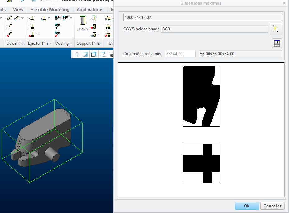
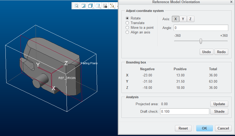
Solution 4 - Manufacturing module (MDO)
Mfg module can measure a boundary box, but you have to do one by one and copy values, no parameter is created.
Solution 5 - Build a custom Toolkit app
You can build your own app for this with Toolkit.
Jose
Feb 02, 2017
03:44 PM
- Mark as New
- Bookmark
- Subscribe
- Mute
- Subscribe to RSS Feed
- Permalink
- Notify Moderator
Feb 02, 2017
03:44 PM
I tried Modelcheck and it works. I'm no expert in this but here is what I did:
Check your config.pro to see where are your modelcheck configs, example:
modelcheck_dir c:\Creo_Configs\MODEL_CHECK_CONFIGURATION
If you don't have copy this folder and use it:
....\Creo 3.0\M000\Common Files\modchk\text\usascii
Then edit the following file:
c:\Creo_Configs\MODEL_CHECK_CONFIGURATION\config\start\default_start.mcs
and add the following line at the bottom:
PRT_ADD_CHK_PARAM DIMS_MAX OVERALL_SIZE
This will create a parameter called "DIMS_MAX" (or choose another name) with the overall size in each part.
Restart Creo, open a assembly
Menu File->Prepare->Modelcheck Interactive->All Levels->Regenerate
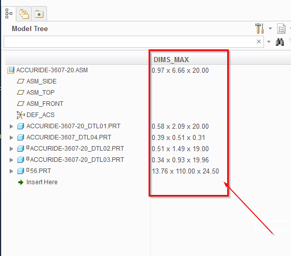
Hope it helps.
Jose
Feb 03, 2017
03:21 AM
- Mark as New
- Bookmark
- Subscribe
- Mute
- Subscribe to RSS Feed
- Permalink
- Notify Moderator
Feb 03, 2017
03:21 AM
That`s quite fascinating. However, I`ve done all the sequence of operations that you mentioned and encountered the problem of not being able to have the parameter `DIMS_MAX` shown in the model tree. How to do that?
Feb 03, 2017
10:01 AM
- Mark as New
- Bookmark
- Subscribe
- Mute
- Subscribe to RSS Feed
- Permalink
- Notify Moderator
Feb 03, 2017
10:01 AM
Just add it to the tree.
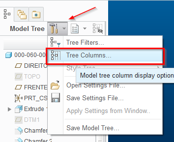
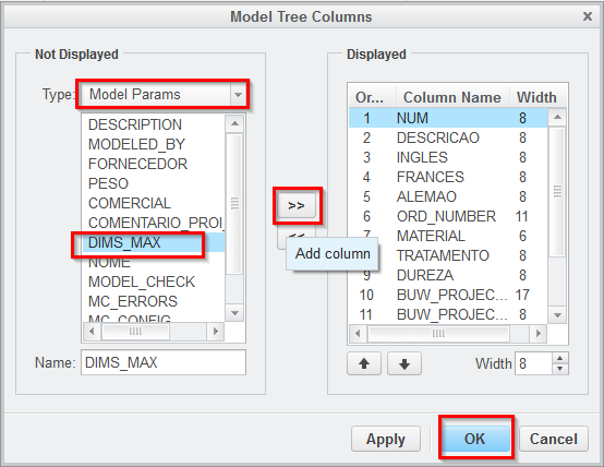
If it doesn't appear in assembly mode, do it in part mode, do "save settings file..." and do "Open settings file.." in asm mode.
EDIT: I found out that you need to change the file condition.mcc. I attached both, replace them and test.
..\config\condition.mcc
..\config\start\default_start.mcs
and the bad news are here: How to get the model size (solid geometry)
