
Turn on suggestions
Auto-suggest helps you quickly narrow down your search results by suggesting possible matches as you type.
Showing results for
Turn on suggestions
Auto-suggest helps you quickly narrow down your search results by suggesting possible matches as you type.
Showing results for
Options
- Subscribe to RSS Feed
- Mark Topic as New
- Mark Topic as Read
- Float this Topic for Current User
- Bookmark
- Subscribe
- Mute
- Printer Friendly Page
swept blend
Jun 25, 2014
04:46 PM
- Mark as New
- Bookmark
- Subscribe
- Mute
- Subscribe to RSS Feed
- Permalink
- Notify Moderator
Jun 25, 2014
04:46 PM
swept blend
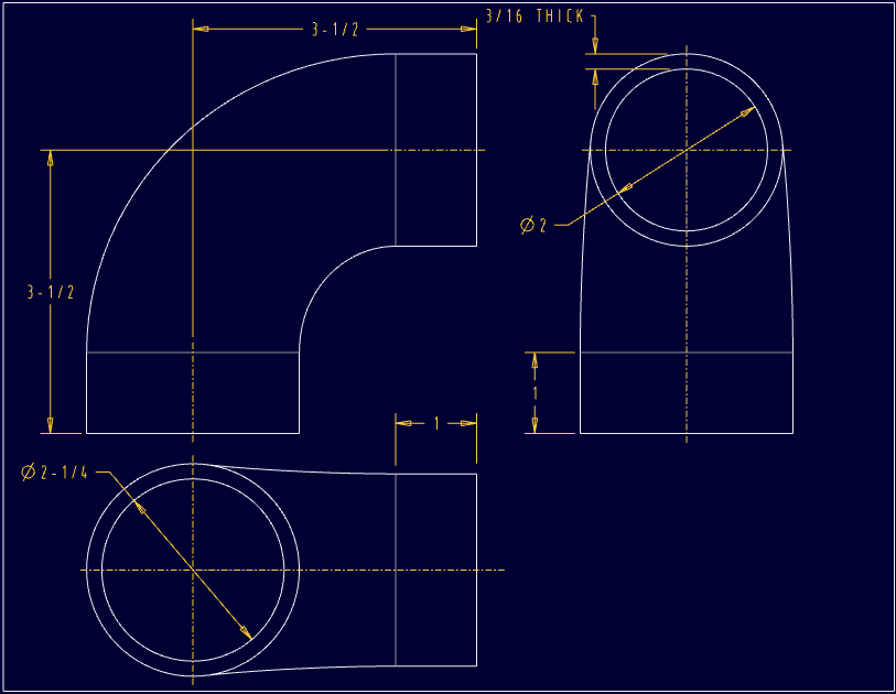
I have created an elbow as a swept blend. It starts out as a circle and ends up as a circle.
I'm apparently doing something wrong.
Again.
Please see the attached file.
The issue is that after the circles are blended, they are no longer circles but splines. I can't measure it in model space and can't dimension it in drawing space.
What am I doing wrong here?
Thanks.
This thread is inactive and closed by the PTC Community Management Team. If you would like to provide a reply and re-open this thread, please notify the moderator and reference the thread. You may also use "Start a topic" button to ask a new question. Please be sure to include what version of the PTC product you are using so another community member knowledgeable about your version may be able to assist.
36 REPLIES 36
Jun 25, 2014
04:53 PM
- Mark as New
- Bookmark
- Subscribe
- Mute
- Subscribe to RSS Feed
- Permalink
- Notify Moderator
Jun 25, 2014
04:53 PM
Probably nothing. Sometimes geometry is promoted to a higher level of abstraction.
You might create sketched datum curves and create use-edge references in making the blend or add a sketched datum curve at each end that is anchored to the edge to give you something to dimension to.
You should still be able to show the arc dimension for the sketches on the drawing, but I can see where you might not be able to see the arcs that are in the sketch.
Jun 25, 2014
05:08 PM
- Mark as New
- Bookmark
- Subscribe
- Mute
- Subscribe to RSS Feed
- Permalink
- Notify Moderator
Jun 25, 2014
05:08 PM
for fun, I created another swept feature consisting of two identical circles on opposite ends of a straight line.
This should give me a cylinder, right?
Same result - the measure tool won't measure it and in a drawing, I can't create a dimension.
In my earlier example, there are four sections, all circles. The first two are the same and the last two are the same. So I should have an elbow with cylinders on either end.
I don't understand what you mean by arcs. The only circular element that isn't a complete circle is the trajectory and I can see that just fine. And it's the only one I can put a dimension on.
Jun 25, 2014
06:28 PM
- Mark as New
- Bookmark
- Subscribe
- Mute
- Subscribe to RSS Feed
- Permalink
- Notify Moderator
Jun 25, 2014
06:28 PM
Works for me...

Jun 25, 2014
06:31 PM
- Mark as New
- Bookmark
- Subscribe
- Mute
- Subscribe to RSS Feed
- Permalink
- Notify Moderator
Jun 25, 2014
06:31 PM
Shown or created?
Jun 25, 2014
06:31 PM
- Mark as New
- Bookmark
- Subscribe
- Mute
- Subscribe to RSS Feed
- Permalink
- Notify Moderator
Jun 25, 2014
06:31 PM
Both
Jun 26, 2014
08:25 AM
- Mark as New
- Bookmark
- Subscribe
- Mute
- Subscribe to RSS Feed
- Permalink
- Notify Moderator
Jun 26, 2014
08:25 AM
That's exactly what I need and would expect.
Yours works but mine doesn't. Hmmmmm. Wonder why?
Jun 25, 2014
06:30 PM
- Mark as New
- Bookmark
- Subscribe
- Mute
- Subscribe to RSS Feed
- Permalink
- Notify Moderator
Jun 25, 2014
06:30 PM
I'm saying arcs as they are a superset to circles.
In many features sketcher circles are promoted to a pair of arcs as part of creating geometry. The splines are a superset to arcs.
The dimensions of the underlying sketcher entities should be available to be shown on the drawing, or if you want to create dimensions, start off with sketched datum curves and related the geometry in the swept feature to them.
Jun 25, 2014
07:00 PM
- Mark as New
- Bookmark
- Subscribe
- Mute
- Subscribe to RSS Feed
- Permalink
- Notify Moderator
Jun 25, 2014
07:00 PM
So it works OK for Antonius. Don't know why.
Are you using straight or smooth blending? I'd open the file if I could.
Jun 26, 2014
03:11 AM
- Mark as New
- Bookmark
- Subscribe
- Mute
- Subscribe to RSS Feed
- Permalink
- Notify Moderator
Jun 26, 2014
03:11 AM
In your example I would do the cylinders at both ends of your tube using revolve or extrude and then blend only the section between them, selecting the resulting edges instead of sketching.
This I believe will also allow you to control the result better, as for example you will be able to add or remove tangency at either end.
Jun 26, 2014
08:26 AM
- Mark as New
- Bookmark
- Subscribe
- Mute
- Subscribe to RSS Feed
- Permalink
- Notify Moderator
Jun 26, 2014
08:26 AM
another work around for something that should work out of the box.
Looks like this silly software turns the arcs to splines. How clever is that?
Jun 26, 2014
08:27 AM
- Mark as New
- Bookmark
- Subscribe
- Mute
- Subscribe to RSS Feed
- Permalink
- Notify Moderator
Jun 26, 2014
08:27 AM
Yes, I can add those dimensions too. But mine don't come in as diameters and you've dimensioned to hidden lines!
Bad draftsman! Bad! <spritzes water>
Jun 26, 2014
09:36 AM
- Mark as New
- Bookmark
- Subscribe
- Mute
- Subscribe to RSS Feed
- Permalink
- Notify Moderator
Jun 26, 2014
09:36 AM
You're not going to be able to measure (distance I assume?) on the blend because Pro/E doesn't know WHERE on that changing surface to measure, because you didn't tell it. In modeling mode you can query-select points on the surface. If you want dwg dims, put in a datum plane and use the interestion of that and the part to give you hard points to measure to.
An SPR is not needed, different/better technique is. 
For this, honestly, I'd use a VSS, and in the curves defining the shape you can put geometry points wherever you want to measure to, AND the VSS will give you better control anyways and assure tangencies where you want 'em.
Jun 26, 2014
09:49 AM
- Mark as New
- Bookmark
- Subscribe
- Mute
- Subscribe to RSS Feed
- Permalink
- Notify Moderator
Jun 26, 2014
09:49 AM
Not distance, but diameter. It should know, after all, I told it!
How should I modify my technique?
Really, this is simple and shouldn't be so hard - starts out as a circle, ends up as a circle. How come I can't measure it? (I know, it's a spline, but why the devil is it now a spline?)
I strongly disagree - a SPR IS needed. This is seriously broke and needs fixed.
I want to look into the elbow, from both ends, and put a diameter dimension on the diameters. Shouldn't need to add planes. There is already a plane there - my sketch is drawn on one - the section is normal to the plane/sketch/trajectory.
It works for Antonius. I'm presuming that he used my model. Why doesn't it work on my system? Antonius, what date code are you using? Is this a bug in my version? I don't have the authority to update my system, so for the time being, that's out.
What is this VSS you speak of? Creo help doesn't recognize it.
Jun 26, 2014
09:52 AM
- Mark as New
- Bookmark
- Subscribe
- Mute
- Subscribe to RSS Feed
- Permalink
- Notify Moderator
Jun 26, 2014
09:52 AM
Ah, Variable Section Sweep. (Should have done the homework. Will have to look into that. I'm sure the help file will explain it.)
Really?
for a simple elbow?
Will I be able to measure the beginning and ending diameters?
Jun 26, 2014
10:11 AM
- Mark as New
- Bookmark
- Subscribe
- Mute
- Subscribe to RSS Feed
- Permalink
- Notify Moderator
Jun 26, 2014
10:11 AM
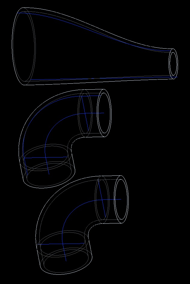
so, here's what I found:
I created an elbow (I love those things!) with the sweep tool
If I create it using the constant section, then afterwards I can measure the diameter
If I change it to the variable section, then the diameter changes to a spline.
Once again, start with a circle, end with a circle, but the system no longer recognizes it as a circle.
Wow.
Jun 26, 2014
10:56 AM
- Mark as New
- Bookmark
- Subscribe
- Mute
- Subscribe to RSS Feed
- Permalink
- Notify Moderator
Jun 26, 2014
10:56 AM
Thanks Steven.
Yes, I know how to get the diameter. Wonder why it's buried so deep? I can also inspect the sections used to drive the swept blend.
Actually, if you don't use vss or swept blend, the sweep will remain a diameter, not a spline surface. Only when you dive down the rabbit hole of the vss or swept blend does it become a spline. Apparently.
But I can live with the kludge of dragging multiple tools out to figure out what the diameter is in the model. The annoying part is in the drawing, where the diameter dimension is so elusive.
Oh well, at least I have my hammer and tongs handy!
Jun 26, 2014
01:47 PM
- Mark as New
- Bookmark
- Subscribe
- Mute
- Subscribe to RSS Feed
- Permalink
- Notify Moderator
Jun 26, 2014
01:47 PM
Yup. And I do get the diameter, but would prefer to avoid dimensioning to hidden lines as that was pretty much beaten out of me in school. Yes, decades ago, but still remember the scoldings..... .
.
And back to beating the dead horse: I should be able to pull a dimension where I want it, dagnabit! If the silly software(TM) knows that it's a diameter in one view, then it should in another!
Jun 26, 2014
11:16 AM
- Mark as New
- Bookmark
- Subscribe
- Mute
- Subscribe to RSS Feed
- Permalink
- Notify Moderator
Jun 26, 2014
11:16 AM
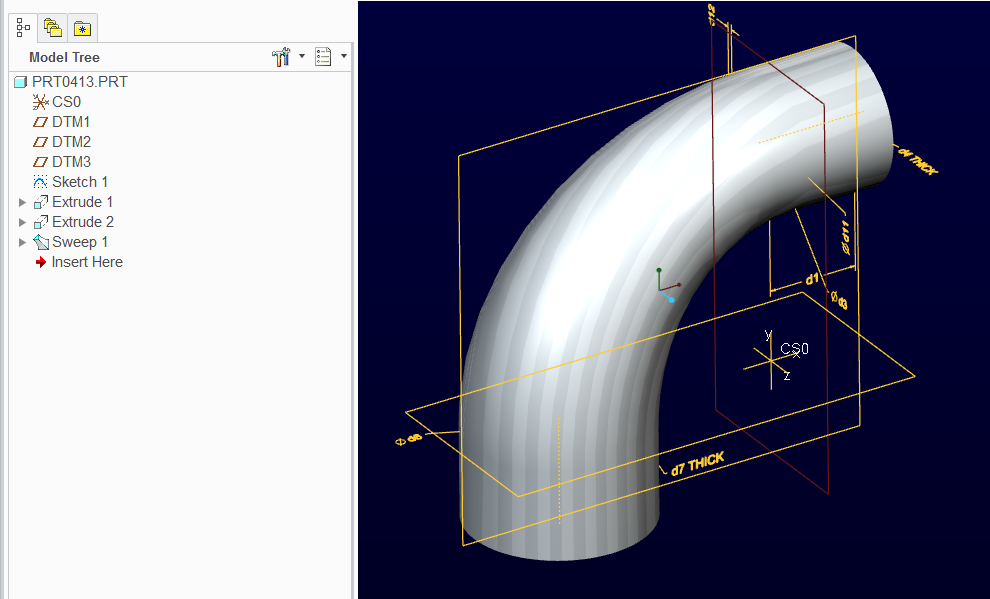
A comparison for fun. The VSS is a little easier, I think, less sections to sketch, and you have more control over the geometry as well. What you can't do with a VSS is reverse curvature or switch between a straight line and curvature or vice versa.
Jun 26, 2014
01:48 PM
- Mark as New
- Bookmark
- Subscribe
- Mute
- Subscribe to RSS Feed
- Permalink
- Notify Moderator
Jun 26, 2014
01:48 PM
Thanks Frank. I'll have a look at these.
Jun 26, 2014
02:41 PM
- Mark as New
- Bookmark
- Subscribe
- Mute
- Subscribe to RSS Feed
- Permalink
- Notify Moderator
Jun 26, 2014
02:41 PM
In general, people that have used Pro|E for a long time and use driving dimensions throughout drawings have learned long ago that we create sketches and dimensions solely for using them in the drawing. Sketches may even be created to have a driven dimension available in the drawing but created in the model. What is more difficult is to consistently have the arc of the spine echoed in the drawing as a centerline so the radius dimension has something to point to.
As for the surfaces or edges of the blended feature not having primitive information available, that is something we long understood as a limitation. Somehow I defined it, so somehow I can access the data I entered.
There are some occasions that policy forbids use of driving dimension on drawings and that only driven drawing dimensions are allowed. Considering Pro|E was never intended to be used this way, means that the policy is not in line with the software (that never happens!). I have the luxury of making drawings however I see fit. And I find myself using both methods and still remain perfectly associative on the overall shape and size of the object I document. But I do often find myself changing the model to suit the need in the drawing. This could well be improved.
Jun 26, 2014
03:29 PM
- Mark as New
- Bookmark
- Subscribe
- Mute
- Subscribe to RSS Feed
- Permalink
- Notify Moderator
Jun 26, 2014
03:29 PM
Frank, there is a neat trick you can use to control tangency in the VSS without a guide curve.
I know this may require a math major to decipher, but in essence, wherever you can incorporate a cos() function, you can get a nice "soft start" on the VSS trajectory...
I made two cylinders and a "spine" that drives the shape. Everything else is covered by relations:
This is the VSS trajectory through the arc only; no blend option needed.
sd6=d3+((d6-d3)/2)-cos(trajpar*180)*((d6-d3)/2)
In simple terms, the sweep starts out 1.5" OD and follows a cosine curve which has a flat state at 1 and -1 (*180) and ends at 2" OD. (d6-d3)/2 manages the difference between the diameters d3 and d6.
In this case... small end =1.75-((1 to -1)*.25).
Now I have cylinders for dimensioning and a smooth cosine transition from one face tot he other without leaving it to the software, or a arbitrary chain curve (if that is not the control you wanted).
Jun 26, 2014
03:40 PM
- Mark as New
- Bookmark
- Subscribe
- Mute
- Subscribe to RSS Feed
- Permalink
- Notify Moderator
Jun 26, 2014
03:40 PM
Nice! Thanks! I debated using a graph, but I figured that a guide curve was the simplest way to understand it for a novice user. I used a conic to cheat and make it simple, tangent, and reasonably smooth.
I really need to get better at math! 
Jun 26, 2014
03:49 PM
- Mark as New
- Bookmark
- Subscribe
- Mute
- Subscribe to RSS Feed
- Permalink
- Notify Moderator
Jun 26, 2014
03:49 PM
Oh and don't forget that you have curvature control if you did this as a boundary blend between the 2 cylinders. Very nice if you need this to be cosmetic...
Jun 26, 2014
04:01 PM
- Mark as New
- Bookmark
- Subscribe
- Mute
- Subscribe to RSS Feed
- Permalink
- Notify Moderator
Jun 26, 2014
04:01 PM
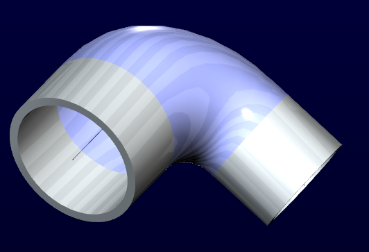
Attached is the STEP file of the Boundary Blend with "curvature" tangency.
Jun 26, 2014
04:17 PM
- Mark as New
- Bookmark
- Subscribe
- Mute
- Subscribe to RSS Feed
- Permalink
- Notify Moderator
Jun 26, 2014
04:17 PM
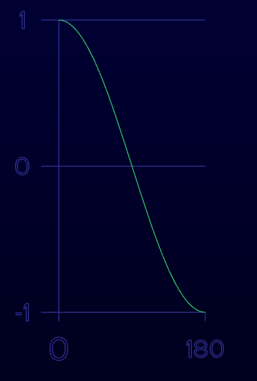
This is the cosine curve (same as a graph would be) for the trajpar statement above:
cos(trajpar*180)
Jun 26, 2014
05:39 PM
- Mark as New
- Bookmark
- Subscribe
- Mute
- Subscribe to RSS Feed
- Permalink
- Notify Moderator
Jun 26, 2014
05:39 PM
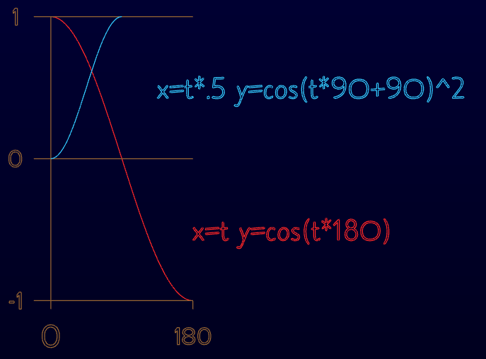
This might help if you want to preserve the trajpar value of 0 to 1.
The cyan curve and related formula will create a "half height" cosine wave offset to invert it.
Play with the squared function by using cubed or higher power and you will get a variation between the start and stop.
The examples below are just the datum curve equations, but you would substitute the "y" entry for any "dn" dimension and replace "t" with "trajpar" in a VSS. Using the cyan equation in VSS relations will assure a tangent/normal start and finish but otherwise equivalent to the normal 0-1 range of trajpar.
Jun 26, 2014
06:05 PM
- Mark as New
- Bookmark
- Subscribe
- Mute
- Subscribe to RSS Feed
- Permalink
- Notify Moderator
Jun 26, 2014
06:05 PM
Cool! I'll have to play with it. I'm a math moron so I avoid it and use geometry wherever possible!
Jun 26, 2014
06:15 PM
- Mark as New
- Bookmark
- Subscribe
- Mute
- Subscribe to RSS Feed
- Permalink
- Notify Moderator
Jun 26, 2014
06:15 PM
Creo Mechanism has forced me to find useful applications for equations.
Otherwise I'm wth you on using geometry.
Jun 27, 2014
11:50 AM
- Mark as New
- Bookmark
- Subscribe
- Mute
- Subscribe to RSS Feed
- Permalink
- Notify Moderator
Jun 27, 2014
11:50 AM
Hah! True!
