
Turn on suggestions
Auto-suggest helps you quickly narrow down your search results by suggesting possible matches as you type.
Showing results for
Turn on suggestions
Auto-suggest helps you quickly narrow down your search results by suggesting possible matches as you type.
Showing results for
- Community
- Creo+ and Creo Parametric
- 3D Part & Assembly Design
- Re: Can`t revolve as a wall in creo sheetmetal.
Options
- Subscribe to RSS Feed
- Mark Topic as New
- Mark Topic as Read
- Float this Topic for Current User
- Bookmark
- Subscribe
- Mute
- Printer Friendly Page
Can`t revolve as a wall in creo sheetmetal.
May 03, 2016
07:26 AM
- Mark as New
- Bookmark
- Subscribe
- Mute
- Subscribe to RSS Feed
- Permalink
- Notify Moderator
May 03, 2016
07:26 AM
Can`t revolve as a wall in creo sheetmetal.
Please help
I want to design a new part using Creo sheet metal. I`ve attached the part which I was able to draw, but problem is I cant revolve it as wall nor I can provide thickness to the same. without thickness error in reading mesh occurs in ANSYS 16.1 . I was able to creat simple hollow cylinder with thickness of 1 mm but I cant create this part with thickness. it fails to generate.
How can i modify my design with having thickness or how can i draw new one with thickness?
This thread is inactive and closed by the PTC Community Management Team. If you would like to provide a reply and re-open this thread, please notify the moderator and reference the thread. You may also use "Start a topic" button to ask a new question. Please be sure to include what version of the PTC product you are using so another community member knowledgeable about your version may be able to assist.
9 REPLIES 9
May 03, 2016
10:48 AM
- Mark as New
- Bookmark
- Subscribe
- Mute
- Subscribe to RSS Feed
- Permalink
- Notify Moderator
May 03, 2016
10:48 AM
Could you make a screenshot of the part ? I can't open it, I get a message telling this has been done on an educative version.
May 03, 2016
04:05 PM
- Mark as New
- Bookmark
- Subscribe
- Mute
- Subscribe to RSS Feed
- Permalink
- Notify Moderator
May 03, 2016
04:05 PM
Thank you for your attention and sorry for this trouble. Here is screenshot of part.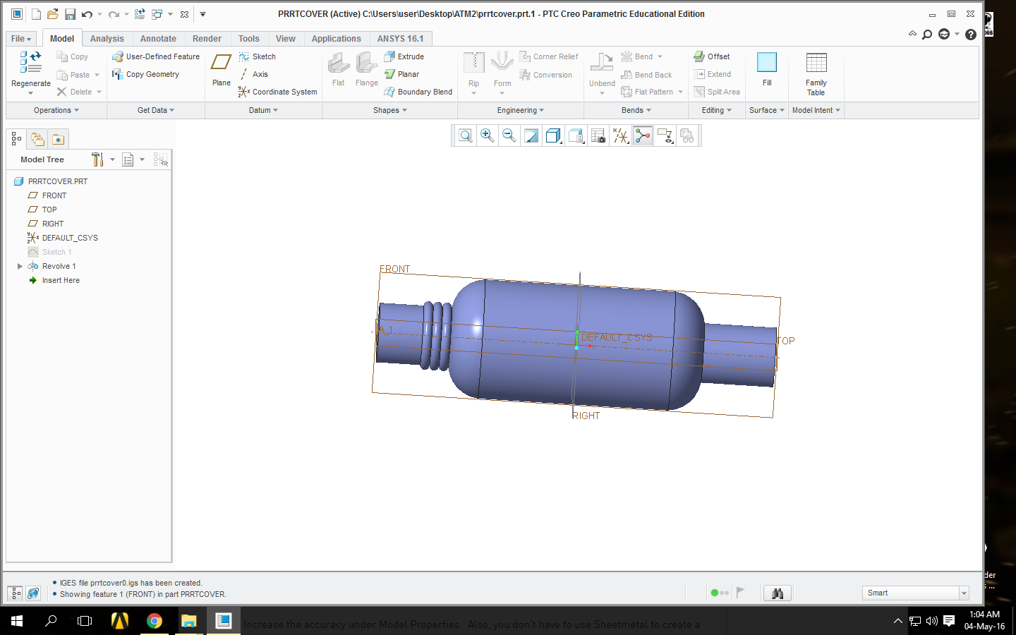
May 03, 2016
04:18 PM
- Mark as New
- Bookmark
- Subscribe
- Mute
- Subscribe to RSS Feed
- Permalink
- Notify Moderator
May 03, 2016
04:18 PM
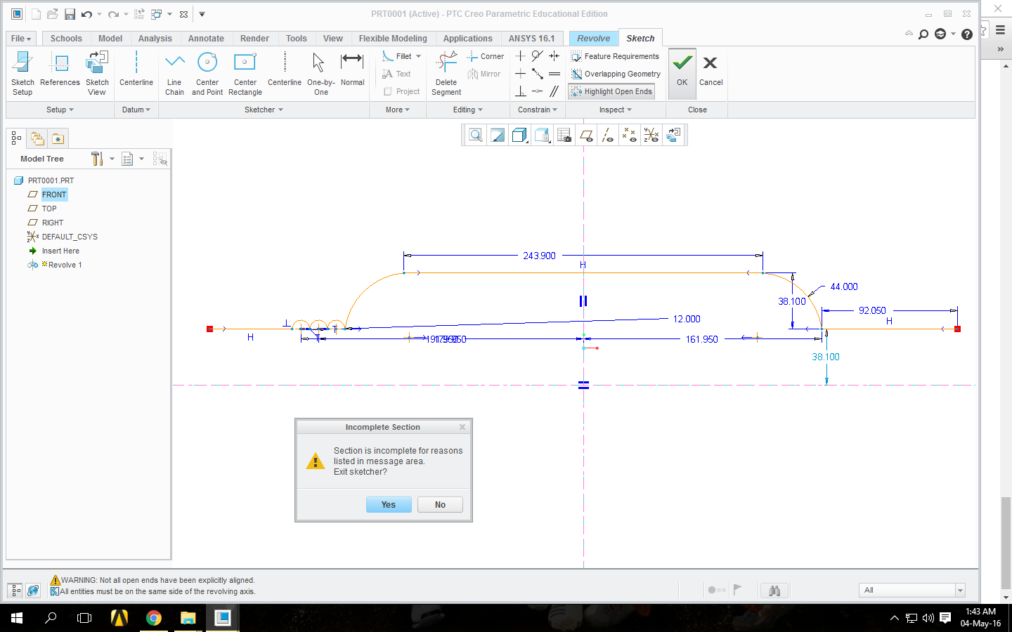
Following is the screenshot of part drawing.

Also I`m facing problem in revolving sketch of this cylinder. I want to revolve it around x-axis but it says `all entities must be on same side of revolving axis` even though they are on same side, see by yourself (this happens after i`ve provided thickness of 1 mm under family table (in Tool menu) otherwise i have sketched upper part without thickness).
May 03, 2016
07:58 PM
- Mark as New
- Bookmark
- Subscribe
- Mute
- Subscribe to RSS Feed
- Permalink
- Notify Moderator
May 03, 2016
07:58 PM
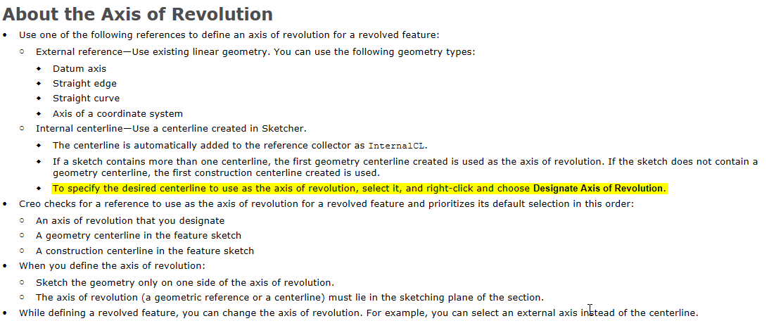
It won't revolve because the in-sketch axis is automatically using the first centerline you sketched and I expect you sketched the vertical one first to mirror some entities.
Since that was the first one, and you have entities on both sides of it, the error message is correct.
You can delete the vertical centerline, but may have to re-do the symmetry, or manually select an axis. I've forgotten which since a couple of decades of remembering to sketch the revolve centerline first has eliminated the need to do anything different. In any case, once you know it's easy to remember.
May 04, 2016
08:05 AM
- Mark as New
- Bookmark
- Subscribe
- Mute
- Subscribe to RSS Feed
- Permalink
- Notify Moderator
May 04, 2016
08:05 AM
Thats what I thought at first, but after drawing it with only x axis and without using mirror command problem is still the same (I cant revolve it)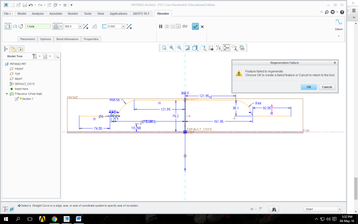
May 04, 2016
09:14 PM
- Mark as New
- Bookmark
- Subscribe
- Mute
- Subscribe to RSS Feed
- Permalink
- Notify Moderator
May 04, 2016
09:14 PM
The first problem you had was the axis of revolution. The new problem is that the section can't be thickened correctly.
I would try eliminating the semicircles that form the ridges or adding fillets where they meet that are at least as large as the desired material thickness.
May 04, 2016
09:57 AM
- Mark as New
- Bookmark
- Subscribe
- Mute
- Subscribe to RSS Feed
- Permalink
- Notify Moderator
May 04, 2016
09:57 AM
From the online help:
May 04, 2016
08:00 AM
- Mark as New
- Bookmark
- Subscribe
- Mute
- Subscribe to RSS Feed
- Permalink
- Notify Moderator
May 04, 2016
08:00 AM
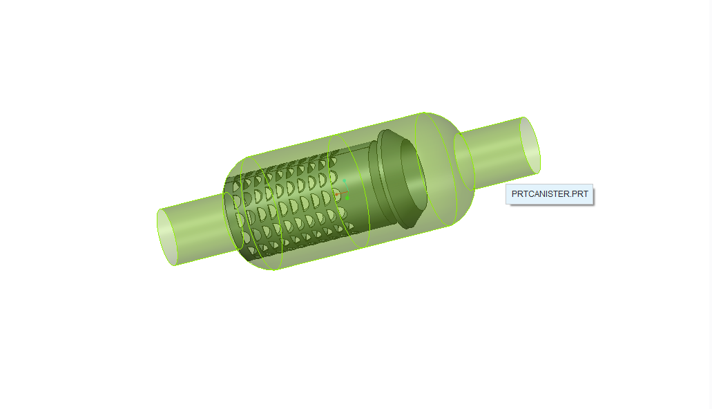
Thank you for your generousness, but this part is just outer cover, whole assembly looks like below and some rings are yet to add at ending. I have done all assembly and run through ANSYS CFX but error occurs saying that error reading mesh (its because I can`t add thickness to it). Are you suggesting that I should draw it in Solid?
May 04, 2016
03:36 PM
- Mark as New
- Bookmark
- Subscribe
- Mute
- Subscribe to RSS Feed
- Permalink
- Notify Moderator
May 04, 2016
03:36 PM
Unless you need to "flatten" the part, I assume this is a tube that is necked down on the ends, create is as a solid. You can revolve it as solid and shell it or revolve it as a surface and thicken. Shelling give you the ability to change the thickness of some walls.
There is always more to learn in Creo.
