
Turn on suggestions
Auto-suggest helps you quickly narrow down your search results by suggesting possible matches as you type.
Showing results for
Turn on suggestions
Auto-suggest helps you quickly narrow down your search results by suggesting possible matches as you type.
Showing results for
Community Tip - Want the oppurtunity to discuss enhancements to PTC products? Join a working group! X
- Community
- Creo+ and Creo Parametric
- 3D Part & Assembly Design
- Re: Creating a part with multiple material layers
Options
- Subscribe to RSS Feed
- Mark Topic as New
- Mark Topic as Read
- Float this Topic for Current User
- Bookmark
- Subscribe
- Mute
- Printer Friendly Page
Creating a part with multiple material layers
Mar 13, 2015
07:21 AM
- Mark as New
- Bookmark
- Subscribe
- Mute
- Subscribe to RSS Feed
- Permalink
- Notify Moderator
Mar 13, 2015
07:21 AM
Creating a part with multiple material layers
I am looking to create a part in Creo that represents a metallised plastic part. The base material is made from a plastic material and it has a very thin (10um) copper layer on top of the plastic with a final nickel layer (5um) on top of the copper.
Is there a way of applying these additional layers of material onto the surface of the existing part?
I intend to carry out some stress analysis on the part if I can achieve this build up of layers in the model.
Solved! Go to Solution.
1 ACCEPTED SOLUTION
Accepted Solutions
Mar 14, 2015
11:12 PM
- Mark as New
- Bookmark
- Subscribe
- Mute
- Subscribe to RSS Feed
- Permalink
- Notify Moderator
Mar 14, 2015
11:12 PM
It is always best to do something before trying to give advice on how to do it 
I had the opportunity to try this and the results were good.
The best part of the attached assembly is that it remains parametric; the worst part of the attached assembly is that it remains parametric.
What that means to say is that you have levels of dependency where any one failure will fail everything. Nothing new here.
Note that the plastic part here is 50mm x 50mm x 20mm. This is important to know when relative accuracy becomes an issue.
At 10um (0.01mm), the offset and merge worked fine. At 5um (0.005mm), the relative accuracy required an adjustment to .0001 (something less than .0012 default).
If I change the plastic part, the clad models change with it, as long as the offsets and cut-outs (merge) features remain viable.
Attached is a full version Creo 2.0 assembly to explore.
Note the feature order explained below the image.
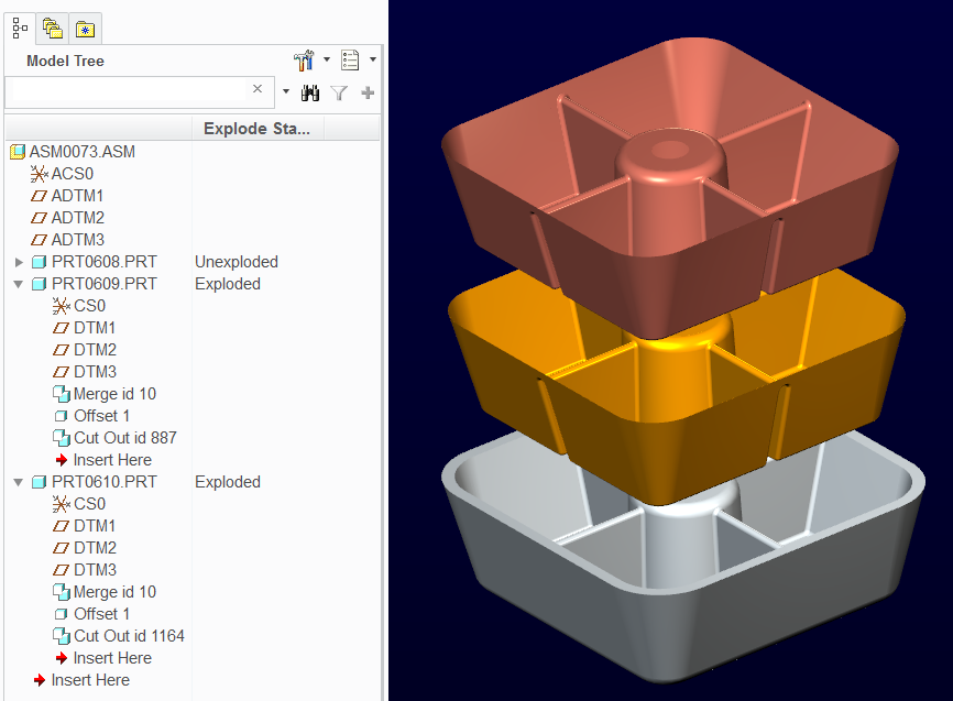
The assembly has the master plastic part assembled.
PRT0609 was added with just CS0 and the default datums (model set to MM)
PRT0609 was Activated and under the Get Data drop-down, you have Merge/Inheritance active. Select this feature.
Select PRT0608 to merge into PRT0609
Open PRT0609 and create a solid offset to the inner surfaces. This takes some knowing, but use the filter (geometry) and select through until you get the "intent surface". Pick all applicable surfaces.
Use offset, and select the non-tapered solid offset option.
Go back to the assembly and activate PRT0609 again.
Again merge PRT0608 but this time use the "remove material" option in the merge dialog.
What remains is the clad solid.
Do the same with PRT0610 only use PRT0609 instead of the plastic master, PRT0608.
Hint: to make offset selection easier for PRT0610, use a larger offset in PRT0609 for the time being. I used 0.5 so I could tell what I was selecting; inside or outside. Once you are done, you can set PRT0609 back to 0.01 and PRT0610 will follow on a regen.
19 REPLIES 19
Mar 13, 2015
01:32 PM
- Mark as New
- Bookmark
- Subscribe
- Mute
- Subscribe to RSS Feed
- Permalink
- Notify Moderator
Mar 13, 2015
01:32 PM
You are describing an assembly of different materials; there's not an option to have a part do this.
Mar 14, 2015
09:14 AM
- Mark as New
- Bookmark
- Subscribe
- Mute
- Subscribe to RSS Feed
- Permalink
- Notify Moderator
Mar 14, 2015
09:14 AM
Yes but I am still unsure as to how I can create an assembly with different layers on the part?
Mar 14, 2015
04:05 PM
- Mark as New
- Bookmark
- Subscribe
- Mute
- Subscribe to RSS Feed
- Permalink
- Notify Moderator
Mar 14, 2015
04:05 PM
You should look at the analysis software for options. It's more likely that you'll need shell elements to handle this; all that will come from the solid will be bricks or tet elements and they will either be highly distorted or very small.
Mar 13, 2015
01:44 PM
- Mark as New
- Bookmark
- Subscribe
- Mute
- Subscribe to RSS Feed
- Permalink
- Notify Moderator
Mar 13, 2015
01:44 PM
Hello, Calum
Your thicknesses are so small that I do not know if Creo will see.
I think we will have to increase the accuracy of your parts to its maximum, have you ever tried.
Now is what these thin layers will really significantly change the characteristics of your parts.
Best Regards.
Denis.
Mar 14, 2015
09:15 AM
- Mark as New
- Bookmark
- Subscribe
- Mute
- Subscribe to RSS Feed
- Permalink
- Notify Moderator
Mar 14, 2015
09:15 AM
I have set my accuracy to the best that Creo can achieve but I am not sure how to apply the additional material surfaces that I mentioned in my original query.
Mar 13, 2015
11:45 PM
- Mark as New
- Bookmark
- Subscribe
- Mute
- Subscribe to RSS Feed
- Permalink
- Notify Moderator
Mar 13, 2015
11:45 PM
Yes, you will need to set the accuracy significantly higher... maybe set it to absolute depending on the part size.
To have different materials, you will need some kind of assembly. That is the only way you can have analysis recognize the different properties.
There are several ways to accomplish the clad models.
As an aside, can you share references of who can do this plating and the kinds of plastics are conducive to the process?
Mar 14, 2015
09:16 AM
- Mark as New
- Bookmark
- Subscribe
- Mute
- Subscribe to RSS Feed
- Permalink
- Notify Moderator
Mar 14, 2015
09:16 AM
It depends on what type of plating that you wish to use and what the intended prupose of the part is for. There are several companies in the UK who can coat a range of plastic materials from ABS to PEEK-type materials.
Mar 14, 2015
01:46 PM
- Mark as New
- Bookmark
- Subscribe
- Mute
- Subscribe to RSS Feed
- Permalink
- Notify Moderator
Mar 14, 2015
01:46 PM
Copper/Nickel is a good EMI/EMC material. That is what peeked my interest. Can you link me to one of these suppliers?
As the how; you might look into the Merge functionality if you wish to remain somewhat parametric.
The easy solution is Offset of the surface making it a solid bigger than the original and then subtracting the original from the merge.
Merge is the Creo equivalent of Boolean operations but it has to be done with outside references.
If you care to post a test part, we can see what it takes to do this in Creo.
Use the advanced editor to attach files.
Mar 14, 2015
11:12 PM
- Mark as New
- Bookmark
- Subscribe
- Mute
- Subscribe to RSS Feed
- Permalink
- Notify Moderator
Mar 14, 2015
11:12 PM
It is always best to do something before trying to give advice on how to do it
I had the opportunity to try this and the results were good.
The best part of the attached assembly is that it remains parametric; the worst part of the attached assembly is that it remains parametric.
What that means to say is that you have levels of dependency where any one failure will fail everything. Nothing new here.
Note that the plastic part here is 50mm x 50mm x 20mm. This is important to know when relative accuracy becomes an issue.
At 10um (0.01mm), the offset and merge worked fine. At 5um (0.005mm), the relative accuracy required an adjustment to .0001 (something less than .0012 default).
If I change the plastic part, the clad models change with it, as long as the offsets and cut-outs (merge) features remain viable.
Attached is a full version Creo 2.0 assembly to explore.
Note the feature order explained below the image.
The assembly has the master plastic part assembled.
PRT0609 was added with just CS0 and the default datums (model set to MM)
PRT0609 was Activated and under the Get Data drop-down, you have Merge/Inheritance active. Select this feature.
Select PRT0608 to merge into PRT0609
Open PRT0609 and create a solid offset to the inner surfaces. This takes some knowing, but use the filter (geometry) and select through until you get the "intent surface". Pick all applicable surfaces.
Use offset, and select the non-tapered solid offset option.
Go back to the assembly and activate PRT0609 again.
Again merge PRT0608 but this time use the "remove material" option in the merge dialog.
What remains is the clad solid.
Do the same with PRT0610 only use PRT0609 instead of the plastic master, PRT0608.
Hint: to make offset selection easier for PRT0610, use a larger offset in PRT0609 for the time being. I used 0.5 so I could tell what I was selecting; inside or outside. Once you are done, you can set PRT0609 back to 0.01 and PRT0610 will follow on a regen.
Mar 15, 2015
12:22 PM
- Mark as New
- Bookmark
- Subscribe
- Mute
- Subscribe to RSS Feed
- Permalink
- Notify Moderator
Mar 15, 2015
12:22 PM
Hello, Antonius,
Magnificent demonstration and construction methodology.
Now it would be interesting to see how Simulate is able to calculate these assemblies and if there is a noticeable difference between the part only
plastic and once covered material.
Best Regards.
Denis.
Mar 15, 2015
01:53 PM
- Mark as New
- Bookmark
- Subscribe
- Mute
- Subscribe to RSS Feed
- Permalink
- Notify Moderator
Mar 15, 2015
01:53 PM
Thanks Denis. I do very little with the simulate lite that I have. Let us know how that works out.
Somewhere in the back of my mind is a thought that simulate will want every model to be set to the same settings including precision.
Others in the community are much better at this than I am.
Mar 16, 2015
04:23 AM
- Mark as New
- Bookmark
- Subscribe
- Mute
- Subscribe to RSS Feed
- Permalink
- Notify Moderator
Mar 16, 2015
04:23 AM
Thanks Antonius that works exactly as I wanted it to do and ti was extremely useful to have a model to go through the steps. Your help is much appreciated.
Mar 16, 2015
04:25 AM
- Mark as New
- Bookmark
- Subscribe
- Mute
- Subscribe to RSS Feed
- Permalink
- Notify Moderator
Mar 16, 2015
04:25 AM
Antonius,
I am just in the exploration stage of metallised coatings on plastic parts but I used a company known as 3DDC who were able to metallise the plastic part.
Mar 16, 2015
03:25 AM
- Mark as New
- Bookmark
- Subscribe
- Mute
- Subscribe to RSS Feed
- Permalink
- Notify Moderator
Mar 16, 2015
03:25 AM
Calum, I don't know your application, but I think that this very thin metal layer is insignificant for the stress and displacement in the plastic part. If this is a stress analysis that is.
Nonetheless, if I were to do this I would put a shell on the surface of the solid, that has the properties of the coating. In this case it is two materials, but as a first guess I would create a shell material as a laminate layup with two different properties, and assign that to the shell...
In the part in the picture I have put shells on the outer surface of the solid, the solid is modeled as usual. Plastic properties fot hte part, the laminate (or metal) properties for the shell...
Mar 16, 2015
04:58 AM
- Mark as New
- Bookmark
- Subscribe
- Mute
- Subscribe to RSS Feed
- Permalink
- Notify Moderator
Mar 16, 2015
04:58 AM
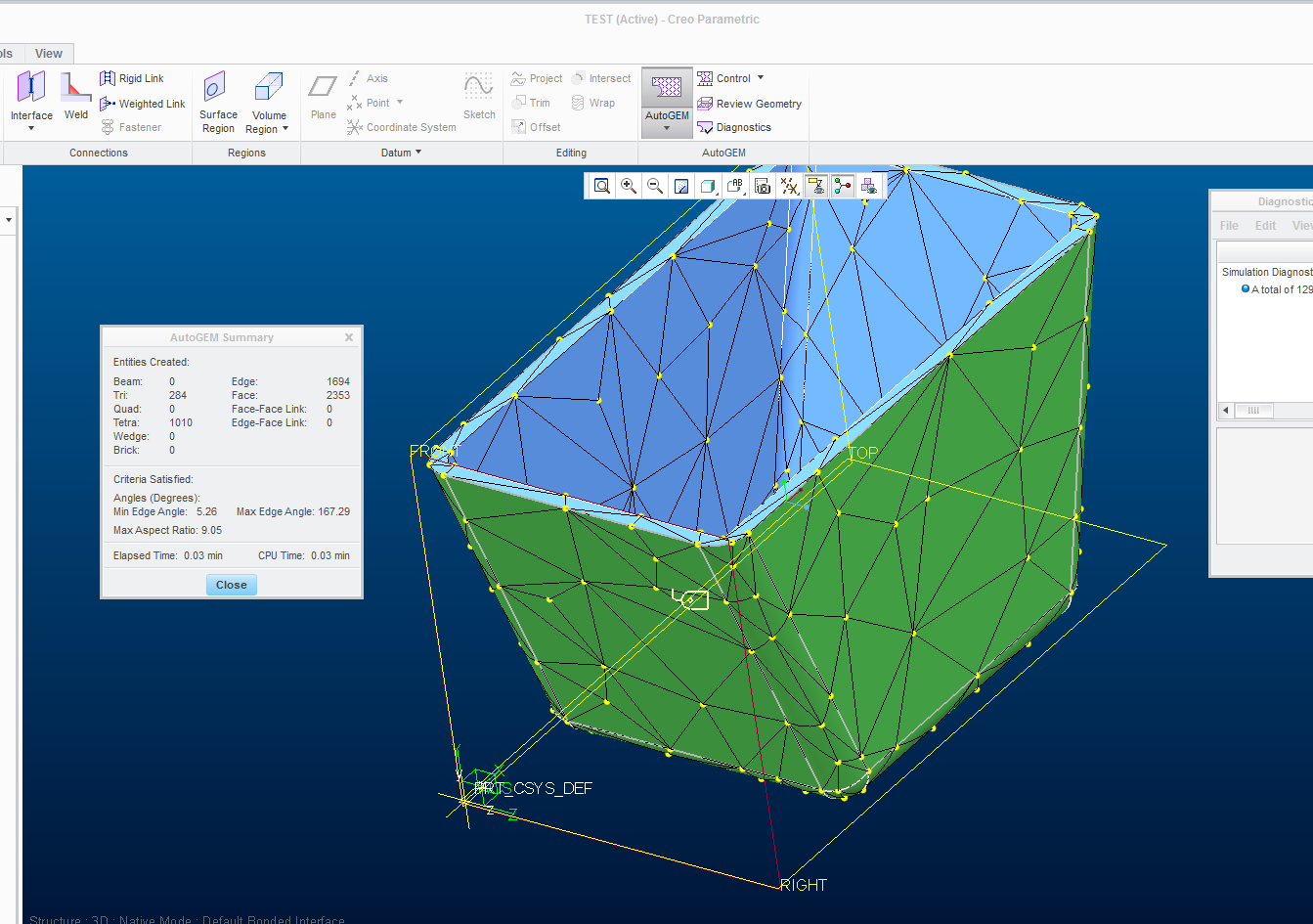
I think I would create a very small but detailed model, using a simple square bit of the base material and the coatings. Apply a load case with tension, and another load case with bending. Compare results of a non-coated block with a coated block. Then (probably) conclude that it has no effect and ignore the coating
Mar 16, 2015
05:10 AM
- Mark as New
- Bookmark
- Subscribe
- Mute
- Subscribe to RSS Feed
- Permalink
- Notify Moderator
Mar 16, 2015
05:10 AM
From an engineering point of view, for a very thin coating you could probably analyse the model as plastic-only, then take the surface strain and compare that to the coating material strength to see whether the coating fractures.
Mar 19, 2015
06:46 AM
- Mark as New
- Bookmark
- Subscribe
- Mute
- Subscribe to RSS Feed
- Permalink
- Notify Moderator
Mar 19, 2015
06:46 AM
Calum,
Here is a model where I created your thin metal layer as a laminate with 0.01 mm of copper and 0.005 mm of nickel. I assigned this laminate property to a shell that I defined on top of the solid surface.
Unfortunately, (correct me if I'm wrong) it is not possible to extract/view shell results separate from the results in the underlying solid elements. This can be done in Mechanica Independent Mode.
Here I created a max prin stress plot for the solid elements and for the shell elements representing the metal layer in Mechanica Independent mode. Note that the stress in the plastic (solid elements) and in the thin metal shell are considerably different, since they have a very different young's modulus.
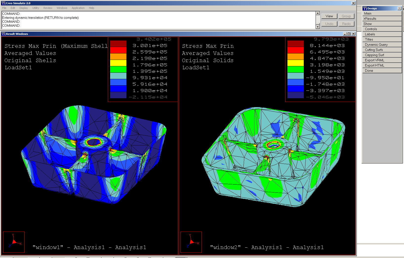
Once again, this very thin layer does most likely not affect the stresses, strains and displacements in the much thicker plastic part. I suspect that it is sufficient to analyze just the plastic part and look at strains on the surface, and verify that the strain on the surface is less than what the metal layer can take.
I hope this helps...
/Mats Lindqvist/
Jun 23, 2016
04:56 AM
- Mark as New
- Bookmark
- Subscribe
- Mute
- Subscribe to RSS Feed
- Permalink
- Notify Moderator
Jun 23, 2016
04:56 AM
Hello Mr. Mats and all,
I will like know if the direction of material layer (NIkel and cupper) in Shell Property Definition is inner to the 3d Solid... I understand that yes.
And
The end layer ... Nickel... is the inner superior layer?
Thanks for the files... They are being very interesting... 😉
Br,
Gorka Garcia
Integral Innovations Solutions
PTC Partner Spain
Jun 23, 2016
07:44 AM
- Mark as New
- Bookmark
- Subscribe
- Mute
- Subscribe to RSS Feed
- Permalink
- Notify Moderator
Jun 23, 2016
07:44 AM
Hi Mr. Mats and all,
I saw inside model 3D in simulate... when click on shell... this was create and pre-view in the middle selection surface
Is normal?
don't will have that be inner in 3d and not middle
Thanks
Br,
Gorka
