
Turn on suggestions
Auto-suggest helps you quickly narrow down your search results by suggesting possible matches as you type.
Showing results for
Turn on suggestions
Auto-suggest helps you quickly narrow down your search results by suggesting possible matches as you type.
Showing results for
Community Tip - Stay updated on what is happening on the PTC Community by subscribing to PTC Community Announcements. X
- Community
- Creo+ and Creo Parametric
- 3D Part & Assembly Design
- Creo Simulate vs ANSYS Workbench contact analysis ...
Options
- Subscribe to RSS Feed
- Mark Topic as New
- Mark Topic as Read
- Float this Topic for Current User
- Bookmark
- Subscribe
- Mute
- Printer Friendly Page
Creo Simulate vs ANSYS Workbench contact analysis w. friction.
Oct 14, 2015
07:52 AM
- Mark as New
- Bookmark
- Subscribe
- Mute
- Subscribe to RSS Feed
- Permalink
- Notify Moderator
Oct 14, 2015
07:52 AM
Creo Simulate vs ANSYS Workbench contact analysis w. friction.
Hello all simulation geeks...
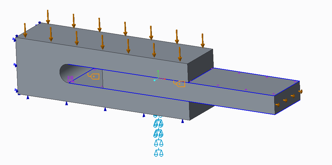
Just for fun, I made a comparison between ANSYS and Creo Simulate 3, to see what the new frictional contact can do in Creo 3. A block with a slot, a plate is located in the slot. The block is squeezed with 20 kN, the plate is pulled out with a force of 1 kN. Coefficient of friction is 0.2, static and dynamic.
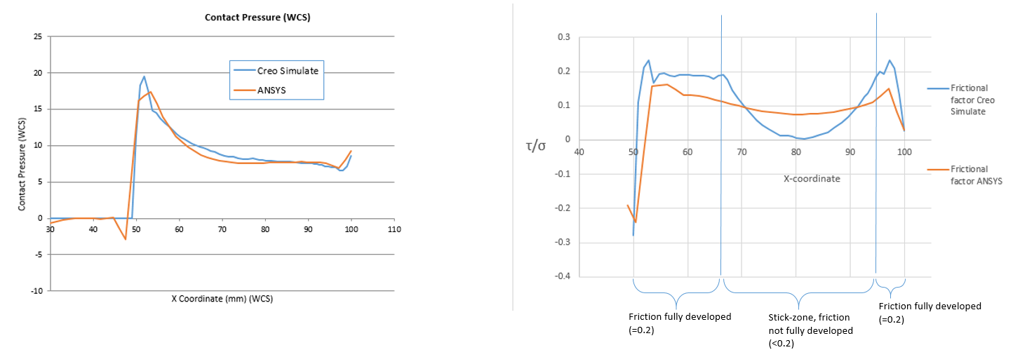
Two graphs showing the contact pressure, and frictional factor, i.e. shear stress at the surface/contact pressure. This should be =0.2 where the friction is fully developed, and <0.2 in the stick zone where friction is not fully developed. Similar results, no particular effort was made to refine the solution, except a slight mesh refinement compared to default mesh...
B.R. Mats L (*for the moment out of assignment*)
Labels:
- Labels:
-
Surfacing
25 REPLIES 25
Oct 14, 2015
08:55 AM
- Mark as New
- Bookmark
- Subscribe
- Mute
- Subscribe to RSS Feed
- Permalink
- Notify Moderator
Oct 14, 2015
08:55 AM
Nice comparison Mats!
Are you saying that Creo Simulate is better, since the frictional factor in the fully developed zones is closer to 2.0 with Creo than it is with Ansys? 
Best Regards,
Jari Elomaa
Oct 14, 2015
09:07 AM
- Mark as New
- Bookmark
- Subscribe
- Mute
- Subscribe to RSS Feed
- Permalink
- Notify Moderator
Oct 14, 2015
09:07 AM
No, if I refine mesh and/or convergence criteria for ANSYS, then I would think it will produce more accurate results aswell. In addition, ANSYS has several different contact formulations. I used "frictional contact" in combination with "Augmented Lagrange" solving technique; I dont know ANSYS well enough to tell which contact algorithm is the most suitable in a given situation. I guess it's a trade-off between time/cost and accuracy, as is often the case. Some contact formulations in ANSYS are computationally effective, but not so accurate on a detailed level.
Oct 14, 2015
12:22 PM
- Mark as New
- Bookmark
- Subscribe
- Mute
- Subscribe to RSS Feed
- Permalink
- Notify Moderator
Oct 14, 2015
12:22 PM
Oh ok. So the main point is that with default settings you may get better results with Creo 3. This is very good to know.
I haven't done any simulations with Creo 3... yet, but I have worked with Ansys for a couple of years and I agree that it tends to require a bit of experimenting with solver settings from time to time. We are only starting to introduce Creo simulations in our R&D and the aim is to get more and more engineers to do some simple simulations and maybe even more complex ones when they get to know the software. Your comparison shows that there are some good and easy capabilities in Creo Simulate, which may prove to be very useful for us.
Thanks again.
Oct 14, 2015
09:03 AM
- Mark as New
- Bookmark
- Subscribe
- Mute
- Subscribe to RSS Feed
- Permalink
- Notify Moderator
Oct 14, 2015
09:03 AM
Bonjour Mats,
Merci pour cette comparaison entre ces deux logiciels.
Avec quel logiciel avez-vous fais les deux graphiques.
Auriez vous la possibilité de mettre le fichier Creo à disposition pour faire des manipulations et apprendre comme model.
Cordialement.
Denis.
Hello Mats,
Thanks for this comparison between these two software.
With what software have you do the two graphs.
Would you have the possibility of putting the Creo file available for manipulation and learn as model.
Kind regards.
Denis.
Oct 14, 2015
09:15 AM
- Mark as New
- Bookmark
- Subscribe
- Mute
- Subscribe to RSS Feed
- Permalink
- Notify Moderator
Oct 14, 2015
09:15 AM
Salut Denis,
Les logiciels sont ANSYS Workbench v15, and Creo Simulate 3.0. Les fichiers Creo sont joints ci-dessous...
/M
Oct 14, 2015
09:57 AM
- Mark as New
- Bookmark
- Subscribe
- Mute
- Subscribe to RSS Feed
- Permalink
- Notify Moderator
Oct 14, 2015
09:57 AM
Bonjour Mats,
Merci pour la réponse.
Re: Avec quel logiciel avez-vous fais les deux graphiques.
Cordialement.
Denis.
Oct 15, 2015
02:41 AM
- Mark as New
- Bookmark
- Subscribe
- Mute
- Subscribe to RSS Feed
- Permalink
- Notify Moderator
Oct 15, 2015
02:41 AM
Denis,
Les deux graphiques sont faits avec Microsoft Excel. Dans Creo Simulate, on peut exporter les chiffres (x,y) d'un graphique à un fichier *.xls. Cliquez "File-Export Excel" (Creo 2.0), dans Creo 3 on clique "File-Save As". Pareil dans ANSYS ...
/M
Oct 15, 2015
06:17 AM
- Mark as New
- Bookmark
- Subscribe
- Mute
- Subscribe to RSS Feed
- Permalink
- Notify Moderator
Oct 15, 2015
06:17 AM
Mats,
Merci pour le renseignement, j'avais pas pensez à Excel avec Creo, avec MathCad, Excel c'est bien.
Cordialement.
Denis.
Oct 15, 2015
06:55 AM
- Mark as New
- Bookmark
- Subscribe
- Mute
- Subscribe to RSS Feed
- Permalink
- Notify Moderator
Oct 15, 2015
06:55 AM
Hi
nice and interesting initiative. Thanks for sharing.
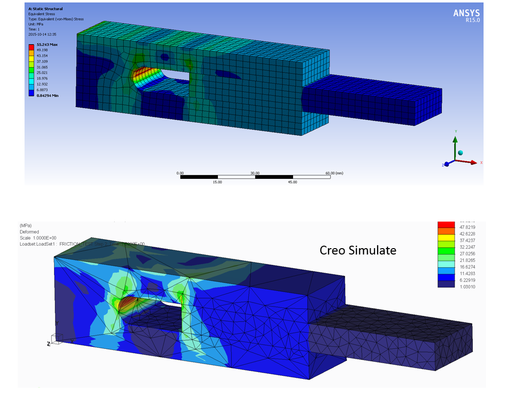
I am wondering why having selected a mesh so different between Ansys and Creo.
Oct 15, 2015
07:17 AM
- Mark as New
- Bookmark
- Subscribe
- Mute
- Subscribe to RSS Feed
- Permalink
- Notify Moderator
Oct 15, 2015
07:17 AM
Creo uses "P-method" which raises the degree of the polynomials that describe the displacement field. ANSYS uses the H-method where the polynomial degree is fixed,for all elements, and is normally 2, i.e. quadratic elements. This means that with the H-method and quadratic elements, stresses and strains can only vary linearly within an element. In creo, the P-level can be raised to 9 and this is done adaptively; in areas with higher stress gradient, the P-level is raised so that a more complex displacement field can be described with a single element. This allows a much coarser mesh than is required if the P-level is fixed to 2, as is the case for Ansys. So the meshing algorithm in Creo is adapted for the P-method, while the meshing functionality in ANSYS is adapted for the H-method. I guess the P-method makes it more difficult to implement nonlinear functionality, which is undoubtedly much better in ANSYS than in Creo Simulate. I think ANSYS has the P-method, but the mesher is not adapted for it, and the P-level is limited to 5 if I remember correctly. And I'm not sure of what nonlinear functionality is supported with the P-method in ANSYS. My guess is that very few Ansys users utilize the P-functionality in Ansys. Long story short: you can't compare Creo Simulate Mesh with ANSYS mesh.
Oct 15, 2015
09:27 AM
- Mark as New
- Bookmark
- Subscribe
- Mute
- Subscribe to RSS Feed
- Permalink
- Notify Moderator
Oct 15, 2015
09:27 AM
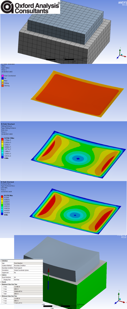
Nice.
My lunchtime meanderings in Ansys following on from my earlier frustration where I could not get it to work in Creo
Below took 2 mins to build and run 20mins to make pics and post.
Oct 19, 2015
09:31 AM
- Mark as New
- Bookmark
- Subscribe
- Mute
- Subscribe to RSS Feed
- Permalink
- Notify Moderator
Oct 19, 2015
09:31 AM
Steve,
Yes. It is exactly the same.
I used the same geometry through the Creo CAD interface for workbench.
Loads and constraints the same (obviously created in workbench). Material might have a slightly different E, nu than the 'steel' in Simulate.
Oct 20, 2015
02:43 AM
- Mark as New
- Bookmark
- Subscribe
- Mute
- Subscribe to RSS Feed
- Permalink
- Notify Moderator
Oct 20, 2015
02:43 AM
(Sorry, I thought the question was for me)
No, I have only presented this here. Perhaps PTC's staff reads this, I don't know.
Oct 20, 2015
05:18 PM
- Mark as New
- Bookmark
- Subscribe
- Mute
- Subscribe to RSS Feed
- Permalink
- Notify Moderator
Oct 20, 2015
05:18 PM
Steven,
I haven't presented the results to PTC.
I will when I get back to the office end of this week
Oct 21, 2015
08:11 AM
- Mark as New
- Bookmark
- Subscribe
- Mute
- Subscribe to RSS Feed
- Permalink
- Notify Moderator
Oct 21, 2015
08:11 AM
Do you seriously expect an answer to that question?
It is like asking Romain Bardret why he is not performing as well as Lance Armstrong.
Oct 21, 2015
09:15 AM
- Mark as New
- Bookmark
- Subscribe
- Mute
- Subscribe to RSS Feed
- Permalink
- Notify Moderator
Oct 21, 2015
09:15 AM
Nov 19, 2015
04:36 AM
- Mark as New
- Bookmark
- Subscribe
- Mute
- Subscribe to RSS Feed
- Permalink
- Notify Moderator
Nov 19, 2015
04:36 AM
Steven,
I haven't forgotten,
I'm waiting for the fixes due out soon to retest before I ask the question.
Oct 15, 2015
10:51 AM
- Mark as New
- Bookmark
- Subscribe
- Mute
- Subscribe to RSS Feed
- Permalink
- Notify Moderator
Oct 15, 2015
10:51 AM
Hi Mats
ok fair enough 
Hopefully regardless of the meshing the results are similar and outcome the same
Best regards
Oct 19, 2015
09:51 AM
- Mark as New
- Bookmark
- Subscribe
- Mute
- Subscribe to RSS Feed
- Permalink
- Notify Moderator
Oct 19, 2015
09:51 AM
One reason why I suspect it is more difficult to implement nonlinear functionality with the P-method, is simply that it seems difficult for PTC to move forward in this area.
Another reason is that in nonlinear problems (I think of plasticity/contact/large deformation) is that the stress/displacement-field may vary in a model (and change as displacement increases) in a way so that it becomes more difficult for Creo's large P-elements to capture what's going on. I can imagine that a large P-element, with poor element geometry (by h-mesh standards) , can more easliy become too distorted for convergence to be possible. With, for example ANSYS h-method, the finer, but better shaped, elements can capture abrupt changes that can occur in nonlinear models, as the deformation increases. This is in fact something I have used when I have had difficulties reaching convergence with nonlinear models in Creo. Instead of SPA convergence method, I refine the mesh and run a "quick check" (basically h-method) analysis, then that might converge. And obviously, a company like Ansys or Abaqus has a different focus to develop working solutions for the analysis specialist, so probably it's also a matter of how much development resources you have available, and how you prioritize those resources.
Oct 19, 2015
11:17 AM
- Mark as New
- Bookmark
- Subscribe
- Mute
- Subscribe to RSS Feed
- Permalink
- Notify Moderator
Oct 19, 2015
11:17 AM
That would go against the philosphy of the P-element solver, where you increase element order rather than element size.
Also, there will be no guarantee that the mesher can actually find a good mesh for a smaller element size, so you might run into issues where the analysis starts running okay and then complains in the middle of the analysis that the mesher fails. An engineer with little experience in FEA would probably have trouble understanding that, and curse at the software.
It would be nice if PTC were to explain how exactly they implement contact in the P-solver. It could also help in making better models.
But one of the drawbacks of Creo Simulate w.r.t. other FEA software is its poor documentation, especially about the underlying theory, so I don't think we'll see that anytime soon.
Oct 20, 2015
02:54 AM
- Mark as New
- Bookmark
- Subscribe
- Mute
- Subscribe to RSS Feed
- Permalink
- Notify Moderator
Oct 20, 2015
02:54 AM
Steven,
Poor background info is a criticism I have made on many occasions.
I would like more background on contact as mentioned above. My knowledge is partly reverse engineered and part remembered occasional notes from PTC when specific questions are answered. Bits of a complete story but never the whole story.
These PTC Global Services documents are not released to the general public and only found by chance or by knowing someone after which they gradually become known by the wider community.
Some earlier documents such as the one you attach were marked as PTC internal only and of course, none of us got copies ...
It is not possible to locate these documents via the PTC support pages (unless that has recently changed) and I point this out whenever possible. They should be part of the help installation.
A cynic may say it is to keep the users ignorant so as to be able to sell services. But I cannot work out if it a premeditated move to maintain the 'positioning of the software' where designers' don't need to know' or a consequence of running a lean ship, There are (were? Is Tad Doxee still around for example?) clearly very clever developers who understand the theory and have tested models etc.
The community is generally unaware of
Where Roland Jakel's and other PTC presentations can be found.
None of us are encouraged to be involved.
Perhaps this is in part a consequence of there being no effective user group any more.
Simulate is very good and getting bettering better and it's CAD integration is brilliant (PTC, please don't quote me out of context), but it will never really begin to deal with software snobbery unless we know more. Again, perhaps this deliberate.
atb
Charles
Oct 21, 2015
08:18 AM
- Mark as New
- Bookmark
- Subscribe
- Mute
- Subscribe to RSS Feed
- Permalink
- Notify Moderator
Oct 21, 2015
08:18 AM
Steven,
Il faut naviguer sur les titres et les différentes années en allemand.
Need to browse titles and different years in German.
https://www.tu-chemnitz.de/mb/MHT/SAXSIM/Archiv/index.php#2015
Denis
Dec 21, 2016
12:29 PM
- Mark as New
- Bookmark
- Subscribe
- Mute
- Subscribe to RSS Feed
- Permalink
- Notify Moderator
Dec 21, 2016
12:29 PM
Dear Mats,
developing a contact algorithm with linear elements is already difficult. In a conventional scheme even quadratic elements rarely converge, and special formulations are needed like that of ABAQUS: the so called 'improved’ formulation elements. For sure penalty tends to smooth everything ... See for example this: http://optimec.ca/news/tetrahedral-elements-available-abaqus-structural-analysis-use/
I have no Idea how PTC made high polynomial degree compatible with contact. Are the Creo Simulate shape-functions of the field really polynomial or are NURBS-diven (high continuity without polynomial instability, but quite challenging to be programmed)?
Regards
Andrea Calaon
Jan 09, 2017
06:45 AM
- Mark as New
- Bookmark
- Subscribe
- Mute
- Subscribe to RSS Feed
- Permalink
- Notify Moderator
Jan 09, 2017
06:45 AM
Andrea,
I too don't know how PTC has implemeted its contact algorithm, so I can't answer your question. Contact is indeed complex and difficult to model. From what I hear, if you need a good contact model with accurate representation of what is happening on a detailed level, MSC Marc is state of the art. I have seen some research publications where this software has been used with success.
I rarely use contact analysis on any more advanced level than what you see in my example here above. If you need to understand what happens on a more detailed level than this, I would recommend physical testing. And even if you use FEA, you will need testing; if you use FEA at the limit of what it is capable of, you need to tune your model, compare with reality, so you understand what is going on, and how to interpret your FE-results relative to your test results.
Feb 03, 2017
05:00 AM
- Mark as New
- Bookmark
- Subscribe
- Mute
- Subscribe to RSS Feed
- Permalink
- Notify Moderator
Feb 03, 2017
05:00 AM
Hi Mats,
Thanks for the wise advices. You are right. Contact issues always need careful experimental validation.
I actually some experience in contact modelling (mainly with with large deformations). I (and a series of colleagues of both industry and academia) prefer that ABAQUS (implicit and explicit) over MSC Marc, and the reason is very specific.
The standard convergence parameters on MSC Marc have been set very "forgiving" in order to have the implicit (Marc does not have explicit!) simulation reach the end.
We had both MSC Marc and ABAQSU and we could see the difference. Most probably if we had set the convergence parameters of Marc equivalent to those of ABAQUS we would have identical results (all the rest being identical). ABAQUS is still putting resources on the contact algorithms.
I am starting to think PTC used hierarchical approximation functions like the old Procision (Apanivich) or the ESRD software (Reliability Guaranteed with Latest Generation FEA Technology). With polynomials high shape ratios (Simulate allow 30 by default!) would mean catastrophe, instead hierarchical functions would behave much better.
