
Turn on suggestions
Auto-suggest helps you quickly narrow down your search results by suggesting possible matches as you type.
Showing results for
Turn on suggestions
Auto-suggest helps you quickly narrow down your search results by suggesting possible matches as you type.
Showing results for
Community Tip - When posting, your subject should be specific and summarize your question. Here are some additional tips on asking a great question. X
- Community
- Creo+ and Creo Parametric
- 3D Part & Assembly Design
- HELP - Impossible Draft
Options
- Subscribe to RSS Feed
- Mark Topic as New
- Mark Topic as Read
- Float this Topic for Current User
- Bookmark
- Subscribe
- Mute
- Printer Friendly Page
HELP - Impossible Draft
Nov 14, 2014
03:48 PM
- Mark as New
- Bookmark
- Subscribe
- Mute
- Subscribe to RSS Feed
- Permalink
- Notify Moderator
Nov 14, 2014
03:48 PM
HELP - Impossible Draft
I need some help from a draft expert on this. I am trying to draft 3 edges that are the same surface all towards the same center.
In the pic below it shows a basic version of the complex edge I'm trying to add draft to.
Currently I have to split this into multiple drafts all with varying angles to get it to work. This doesn't work though because I need the 2 open ends to have the same draft angle. Please feel free to ask questioons if I haven't explained this welll enough.
I'm attaching the Creo file as well if anybody wants to show me an example rather than explaining it.

Solved! Go to Solution.
1 ACCEPTED SOLUTION
Accepted Solutions
Nov 19, 2014
01:26 PM
- Mark as New
- Bookmark
- Subscribe
- Mute
- Subscribe to RSS Feed
- Permalink
- Notify Moderator
Nov 19, 2014
01:26 PM
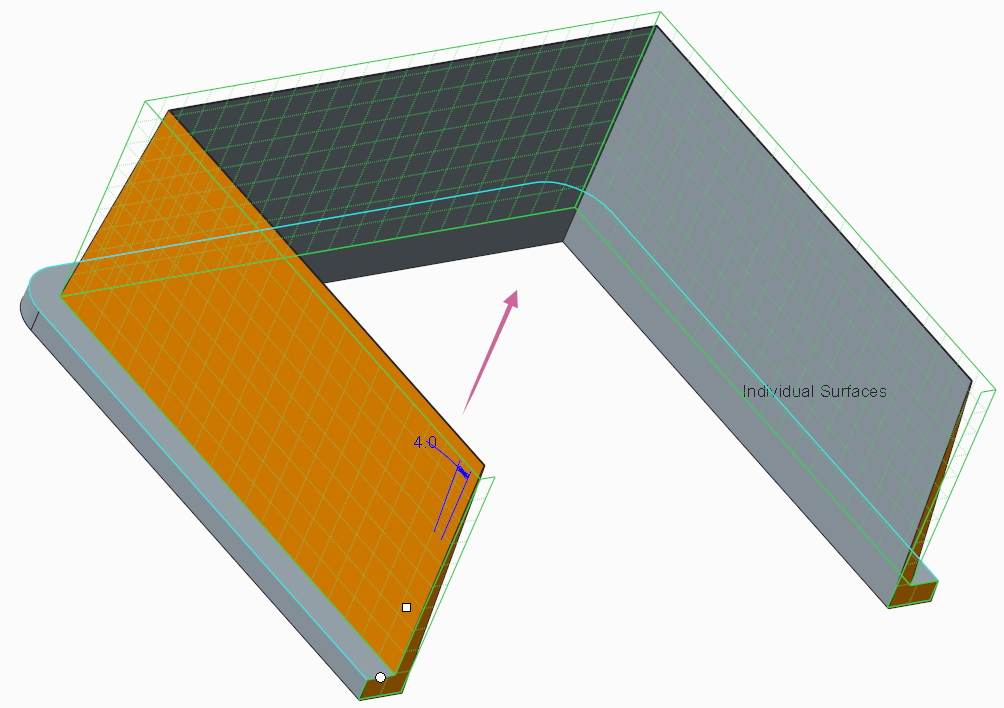
If you are referring to the second image in my post above, then here's how I did it:
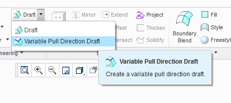
Use the "Variable Pull Direction Draft"
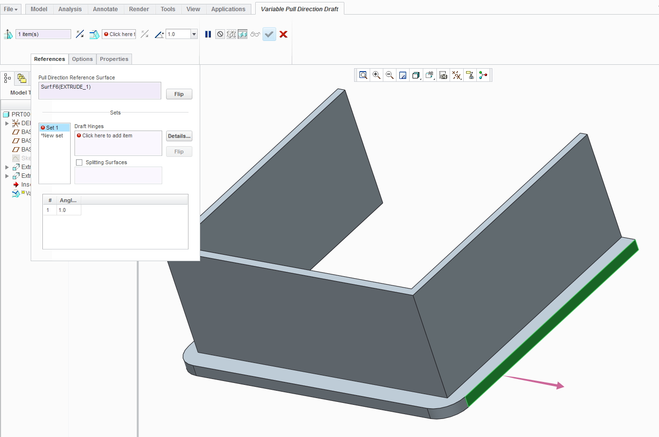
Once in the tool, select this surface to define your pull direction:
Then select the edge that is shared by the surface above and the surface that you want drafted. Then hold down shift and select the other end of the curve created by this edge as shown below:
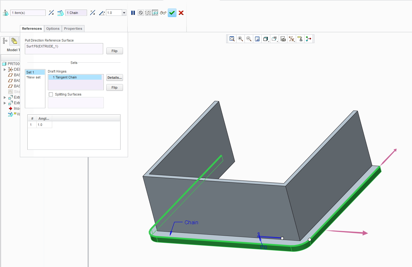
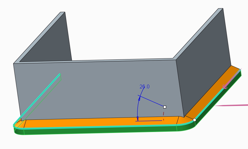
Finally, switch the direction of the draft hinge so it works correctly:
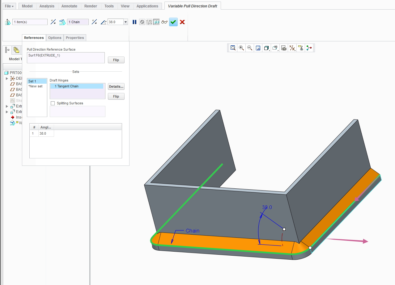
Now you can adjust your angle. Note that this method allows you to create drafts with angles larger than 30 degrees that you are limited with in the normal draft tool (except Creo 3.0 and beyond). Hope this helps. If you were referring to the first image in my post above, I can give specific instructions for that too, although that method is more straight forward with the normal draft tool.
6 REPLIES 6
Nov 14, 2014
05:38 PM
- Mark as New
- Bookmark
- Subscribe
- Mute
- Subscribe to RSS Feed
- Permalink
- Notify Moderator
Nov 14, 2014
05:38 PM
I don't understand what surfaces you are trying to draft. Do you mean like either of the two following images?
Nov 14, 2014
05:42 PM
- Mark as New
- Bookmark
- Subscribe
- Mute
- Subscribe to RSS Feed
- Permalink
- Notify Moderator
Nov 14, 2014
05:42 PM
I think if you can markup a couple of 2D or 3D screen shots to show the parting line splits in the mold it would clarify what you are trying to do, it is not clear from your verbal description. I can see multiple options for splitting the mold to make this piece, all drafted differently.
========================================
Involute Development, LLC
Consulting Engineers
Specialists in Creo Parametric
Involute Development, LLC
Consulting Engineers
Specialists in Creo Parametric
Nov 19, 2014
10:44 AM
- Mark as New
- Bookmark
- Subscribe
- Mute
- Subscribe to RSS Feed
- Permalink
- Notify Moderator
Nov 19, 2014
10:44 AM
The post made by Eric Terrell is exactly what I am trying to do. I couldn't get the edges to meet correctly at the corners though. I had to remove all the round from my original flanges and then do it in 3 seperate sections after that. Maybe you could expand on what you did to create that feature...Maybe i'm missing something.
Nov 19, 2014
01:26 PM
- Mark as New
- Bookmark
- Subscribe
- Mute
- Subscribe to RSS Feed
- Permalink
- Notify Moderator
Nov 19, 2014
01:26 PM
If you are referring to the second image in my post above, then here's how I did it:
Use the "Variable Pull Direction Draft"
Once in the tool, select this surface to define your pull direction:
Then select the edge that is shared by the surface above and the surface that you want drafted. Then hold down shift and select the other end of the curve created by this edge as shown below:
Finally, switch the direction of the draft hinge so it works correctly:
Now you can adjust your angle. Note that this method allows you to create drafts with angles larger than 30 degrees that you are limited with in the normal draft tool (except Creo 3.0 and beyond). Hope this helps. If you were referring to the first image in my post above, I can give specific instructions for that too, although that method is more straight forward with the normal draft tool.
Dec 02, 2014
11:11 PM
- Mark as New
- Bookmark
- Subscribe
- Mute
- Subscribe to RSS Feed
- Permalink
- Notify Moderator
Dec 02, 2014
11:11 PM
Interesting Eric,
Used ProE/Creo for years and was not familiar with this aspect of draft. As Suzie suggested I have made complex drafts many times using VSS surface modelling. Will give your suggestion a try.
Regards, Brent
Nov 19, 2014
04:23 PM
- Mark as New
- Bookmark
- Subscribe
- Mute
- Subscribe to RSS Feed
- Permalink
- Notify Moderator
Nov 19, 2014
04:23 PM
I believe you could also use Variable Section Sweep using the normal to projection option. Your draft direction reference would be your normal to projection reference and your trajectory would be the same edge Eric shows in his answer. Using VSS for drafting also allows you to go beyond the 30 degree limit.
