
Turn on suggestions
Auto-suggest helps you quickly narrow down your search results by suggesting possible matches as you type.
Showing results for
Turn on suggestions
Auto-suggest helps you quickly narrow down your search results by suggesting possible matches as you type.
Showing results for
Community Tip - Did you know you can set a signature that will be added to all your posts? Set it here! X
- Community
- Creo+ and Creo Parametric
- 3D Part & Assembly Design
- Marking point for welding part on sheet metal plat...
Options
- Subscribe to RSS Feed
- Mark Topic as New
- Mark Topic as Read
- Float this Topic for Current User
- Bookmark
- Subscribe
- Mute
- Printer Friendly Page
Marking point for welding part on sheet metal plate
Oct 01, 2014
05:48 AM
- Mark as New
- Bookmark
- Subscribe
- Mute
- Subscribe to RSS Feed
- Permalink
- Notify Moderator
Oct 01, 2014
05:48 AM
Marking point for welding part on sheet metal plate
Hi,
We use marking points on our dxf files on the plate for the position (center) of welding the part.
It is a sketch with a diameter of 1mm on the surface. The machinery recognize this sketch of 1mm and will automatically make a punch mark on this place.
For this we don't need to add dimensions on the drawing for placing the part.
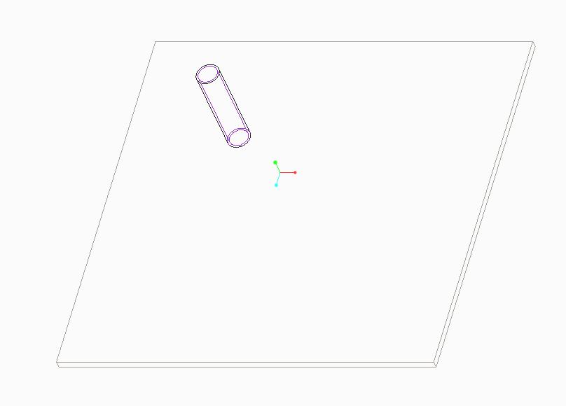
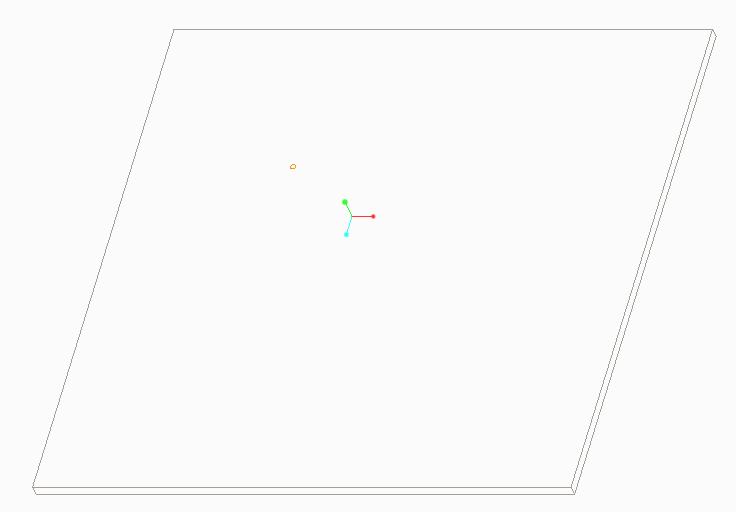
Now we created a subassembly of the part and made the sketch in the subassembly. We made 2 simpl. reps, display drawing (figure 1) and display drawing digital (figure 2). Actually I prefer only a sub part.
For sheet metal it is a problem because the coordinate system I had to place it in the plate. Because it needs to follow the correct position in unbend state.
I prefer to use skeletons for my coordinate systems.
Are there any good ways to do this properly?
Kind regards, Koen.
Labels:
- Labels:
-
Surfacing
1 REPLY 1
Oct 01, 2014
04:23 PM
- Mark as New
- Bookmark
- Subscribe
- Mute
- Subscribe to RSS Feed
- Permalink
- Notify Moderator
Oct 01, 2014
04:23 PM
Koen, I am not sure I understand the challenge. You plate does not have a circle but a CSYS where the circle is shown in the second image.
If you are trying to have mating features for the assembly in both bend and unbent states, you can create an axes, a hole, or anything that does follow the unbend process (flat pattern too). I recently reported a bug with this respect, but the idea is that you can have features follow the bend and unbend operations. You have to be a little careful about what you use for assembly references.
Many things will follow the bend state. Maybe a little more information on the full process will be helpful.
