
Turn on suggestions
Auto-suggest helps you quickly narrow down your search results by suggesting possible matches as you type.
Showing results for
Turn on suggestions
Auto-suggest helps you quickly narrow down your search results by suggesting possible matches as you type.
Showing results for
Community Tip - Visit the PTCooler (the community lounge) to get to know your fellow community members and check out some of Dale's Friday Humor posts! X
- Community
- Creo+ and Creo Parametric
- 3D Part & Assembly Design
- So, they want me to learn SolidQuirks.....
Options
- Subscribe to RSS Feed
- Mark Topic as New
- Mark Topic as Read
- Float this Topic for Current User
- Bookmark
- Subscribe
- Mute
- Printer Friendly Page
So, they want me to learn SolidQuirks.....
Nov 03, 2015
07:19 PM
- Mark as New
- Bookmark
- Subscribe
- Mute
- Subscribe to RSS Feed
- Permalink
- Notify Moderator
Nov 03, 2015
07:19 PM
So, they want me to learn SolidQuirks.....
Honestly, the way PTC has completely dropped the ball when it comes to getting Pro/E into colleges is the main reason. One of the reasons the SW users hers (who never actually really put forth any effort to LEARN Pro/E) are pushing for it is the lack of Engineers who can use Pro/E fresh from school. I'd rather them hire experienced Engineers, but maybe that's just me....
So, I think it will look good on MY resume, so I'm going to put effort into learning it. I will give it a fair evaluation after I've learned enough about it's capabilities, though I will say it will probably be very much like friends who are very experienced users in both and in general are saying. We'll see. There are some things I like about SW from what I saw already. I'm curious about the GUI's all the i-phone kiddies seem to love......
And, from seeing their work, I'm sure I'll be more fluent in SW than they ever became in Pro/E.....and I'm also sure I'll even be better in SW than any of them. Only one of them even remotely impresses me in SW.
So, my questions to those who use both is:
1. What should I expect?
2. What are the shortcuts/tricks?
3. What is the easiest/best approach to learn it quickly and fluently?
4. Using surfacing and the advanced features like I do, what are the comparable features and building methods in SW?
Anything else you think I might want to know.
Grazie!
Stay tuned dear friends! 
Solved! Go to Solution.
Labels:
- Labels:
-
Surfacing
104 REPLIES 104
Nov 18, 2015
09:54 AM
- Mark as New
- Bookmark
- Subscribe
- Mute
- Subscribe to RSS Feed
- Permalink
- Notify Moderator
Nov 18, 2015
09:54 AM
I checked, and SW files are not compatible with CATIA files. I was hoping that maybe if my boss gets his way and we're stuck with SW, that a I could at least get us a couple seats of CATIA for the ID work I do....but no go.
So, I'd love to get creo 3 running (looks like that will happen soon - yay!), and get a copy or 2 of ICEM surf to to the real ID stuff.
Funny you should mention Harley, I was contacted by one of their HR guys and they really wanted me to go work for them at their design center. I would have jumped at the chance....except that it would be in the Milwaukee area, and I can't do that. I have an 8 yr-old daughter here, and love CO, and I can't consider moving. Too bad, I think I would have loved the job, and the chance to be doing a lot of nothing but creative ID work.
Nov 18, 2015
10:10 AM
- Mark as New
- Bookmark
- Subscribe
- Mute
- Subscribe to RSS Feed
- Permalink
- Notify Moderator
Nov 18, 2015
10:10 AM
Frank,
You had better check to see it SW can handle the ICEM/Surf data precision when and if SW can bring it in. One good thing with Creo is ICEM and it had to play somewhat nice together back in time. Even though they are not exactly compatible, they can "see" one another.
Also, learning Icem is somewhat of a non starter, career-wise. Very few companies use it in North America, Harley being one and Peterbilt down in Denton are the only two I know at this point. I am not sure if Volvo does or if they went to Catia. I think Catia but there may be some remnants of ICEM.
Otherwise, you may need to move to Europe to get full use out of your new skills. ;o)
Nov 13, 2015
09:30 AM
- Mark as New
- Bookmark
- Subscribe
- Mute
- Subscribe to RSS Feed
- Permalink
- Notify Moderator
Nov 13, 2015
09:30 AM
Not all companies need those "powerful toys" you talk about. And Simplified Reps don't work for all designs. We have basically nothing to simplify in our designs and frequently have to do drawings of 20k+ part assemblies. There is no choice but to sit and wait, and heaven help us if PTC is willing to try and show us a way of improving things. Every time we mention this they say, "oh look at this Vermeer excavator that you just hide everything inside the cab because you're working on the tracks." Well that's great, but EVERY single piece of our assembly is visible when working on it, because there is no enclosure. It sits in a big concrete pit. And you can't simplify a bunch of pipes welded together, simple welded brackets, and bent sheet weldments. When working with very simplistic, yet large part count assemblies, no one has ever given us a single helpful tip on increasing our speed or efficiency.
It all comes down to what you're modeling and what your company NEEDS. There is no one size fits all. We're making Creo work, and now have a corporate directive that all business units are supposed to use it. Looks like I'll be with it for a while, but that doesn't make it easier to use, or some God of a software that fixes everything where the "little guys" can't compete.
As for Tesla, I don't know when they started this project, but SW has had PDM options for over a decade.
As for your SW expert for 15 years comment... that's pathetic on your part. I was using SW 15 years ago. I was creating injection modeled parts, and complex faces/models w/o using surfacing, and never ran into something I couldn't model with it. Call it what you want, but I did EVERYTHING I needed to in SW. So how does that make me not believable?
It never fails... 15 minutes on this forum and the "Creo users are better than you" attitude gets me everytime.
Nov 13, 2015
10:17 AM
- Mark as New
- Bookmark
- Subscribe
- Mute
- Subscribe to RSS Feed
- Permalink
- Notify Moderator
Nov 13, 2015
10:17 AM
Well, just in the short time I spent on SW, it IS missing the toys I frequently use. So, yes, I, as the lead CAD Guy in this facility, bevlieve I need those powerful functions. No graph feature? No trajpar? No multi-set rounds? Just because you have a complex PART (big block with 1,000 straight holes qualifies), doesn't mean you're creating complex geometry. And it sounds like you're not using simplified reps correctly. The idea is to suppress everything you're not actually going to model, modify, or reference. It has nothing to do with whether you SEE it or not. And, when loading the assembly in the first place, you can choose to start using a simplified rep of only, say, 100 parts. This DRAMATICALLY increases loading speed, and decreases memory usage. Also, if you MUST see all 20k parts, you can create a rep that has only the 100 you need to work on at full strength, and use simplified graphical representations for all the rest. That way you see them all, but they can't be modified and are extremely light weight.
I'd say you guys need more training before you complain about creo, because it HAS the tools you need, you just don't know how to use them. Me, I'm finding SW doesn't HAVE the tools.
Edit: It appears you guys make water filtration equipment? If that's the one, in looking at pics form the various sites, there may be complex assemblies, but no complex geometry.
For reference, I do Industrial as well as Mechanical design, so for me, I need those powerful tools. In fact, I'm pushing to get MORE powerful surfacing tools.
Nov 13, 2015
01:33 PM
- Mark as New
- Bookmark
- Subscribe
- Mute
- Subscribe to RSS Feed
- Permalink
- Notify Moderator
Nov 13, 2015
01:33 PM
Frank,
I clearly stated that Creo is certainly better for some people. I also clearly stated that what I currently work on is very simplistic. I've never needed a graph feature at any of my jobs. Are there tons of people that do? Probably. My exact point is that not everyone does, so not everyone eventually needs bigger toys.
I know how to use simplified reps. I used the general terms "see" because it applies to models and drawings. I realize you are suppressing (excluding) models/features in reps. This doesn't help though when you need a BOM to list ALL items, or you need to balloon all items, or you need to have a view that shows all items. It also doesn't help when you're working in a drawing (which therefore has the model loaded) and you have to jump back in the model to revise something. Simplified reps don't work in all cases (like the screenshot I posted about 6 comments above.)
I completely agree we need more training. I am certain that Creo has some tools that will help. However, I do not know if it justifies the slower modeling speed, drawing creation, and learning curve that comes with it. Again, for some companies, absolutely. For us, I don't know. Also for you to say that Creo HAS the tools we need, is a wishful statement. Without knowing what we do, the best you can say is that you THINK it has what we need.
And for the 15th time... I NEVER SAID WE MAKE COMPLEX GEOMETRY. The only time I mentioned complex geometry was when I said that I was doing complex molded parts back in 2001 w/ SW.
SW may not be for you. That's fine. I said it wasn't for everyone. The general comments by Bart about how everyone wants better toys, and SW didn't have PDM, and you can't do G2 or G3 are what drive me nuts. Two are completely false, and most of his other points only apply to the vast minority of CAD users.
Nov 05, 2015
06:48 PM
- Mark as New
- Bookmark
- Subscribe
- Mute
- Subscribe to RSS Feed
- Permalink
- Notify Moderator
Nov 05, 2015
06:48 PM
Soooo, I got on the SW forum today and posted up about learning it from Pro/E, and asked for advice and comparative advanced features and.......crickets. Wow. Maybe they didn't like that I claimed to be a expert Pro/E user?
I also posted a bunch of the pics I have here in my photo album.
I also found a thread where people were posting pics of things they did. While I saw some assemblies with many parts, or parts with many features (a lot less of those), what I really did NOT see, was parts or assemblies with complex SHAPES. Nothing really sculpted or obviously "surfaced". In 115 pages, what VERY little I found was of the "hack and slash and add rounds" variety, nothing truly surfaced. I think THAT tells me a lot about what I needed to know about SW's (lack of) Industrial Design capabilities.
But, from what I've seen over the years, tried myself, and have read here and elsewhere, this is pretty much what I expected.
Nov 05, 2015
07:32 PM
- Mark as New
- Bookmark
- Subscribe
- Mute
- Subscribe to RSS Feed
- Permalink
- Notify Moderator
Nov 05, 2015
07:32 PM
Your pretty close there, Frank. The words PTC and Creo makes eyes glaze over at the SW forum.
This was my foray into the "where the heck is..."
Does Solidworks have an equation curve based on... | SOLIDWORKS Forums
Definitely more hacks on the SW side then on the more formal Creo "WorkAround^tm" crowd.
Nov 06, 2015
06:57 AM
- Mark as New
- Bookmark
- Subscribe
- Mute
- Subscribe to RSS Feed
- Permalink
- Notify Moderator
Nov 06, 2015
06:57 AM
Frank,
The reason you will not find truly "surfaced" things is because SW is not really a "surfacing" tool, as a first cause software like Pro, Catia, NX and others are. That does not mean you cannot create some interesting things. You just have to do it with a different method. Doug Schaefer made the point. SW was "written" to fill the mid-range gap between the Big Dogs and Chihuahua's of the CAD world. It's really just Old School Boolean modeling in a new dress. The key is it's been "marketed" for years as the Cat's Ass when it really isn't like Bart Brecha demonstrated. I think that is why it "makes sense" and "seems easy" to engineering academia. They see it every day in class. Remember, EVERY single CAD package's root functionality can be found in Calculus 1-4 text books. From there it's free reign whether they add Mechanics, Physics, Chemistry, etc..... and then from there it up to them to "make it easy" or not.
The other point I want to touch upon is SW model robustness. I have read the experiences of many that say their SW models are 'fragile' and fall apart upon revision (I.E. as in Hack modeling). I am not saying they were sloppy as they did not say that. But maybe I am the anomaly as I have not had such experiences with SW models 'failing' without the normal and customary reasons as the cause. I use what would be called robust techniques in the Pro World on my SW models and I seem to sail through it all pretty much unscathed. I have been at t his CAD stuff too long the 'hack my way through'. I know that if I cheat...it will bite me badly later...and always at the most inopportune moment.
If I were in the Witness Stand and I were asked what my biggest problem(s) with SW are, my answer(s) would be:
1. The way it 'manages' file locations and it's inability to 'know' where to pull and store working files is the Right Achilles Heel. (That includes files with the same name in different locations too).
2. The fact I must have, what I call, 'All the plates' spinning at one time is the Left Achilles Heel. If I am developing something and I want to see a "what if" and I move from part to part, assembly to assembly (I.E. window to window)....I DO NOT WANT TO HAVE TO SAVE MY FILES! Sorry did I say that loudly? SW, to my knowledge, has ZERO rev control while the 'plates are spinning'. (I.E. "In Session". But SW does not have "In Session" like Pro). It's like walking a tight-rope without a net...eventually I die in a horrific 12,500 foot fall onto the jagged rocks below.
All the rest of its 'quirks', I can deal with.
Happy SolidWorking, Frank.
BTW...are you an ID guy? I heard you mention something in the thread.
Nov 06, 2015
10:14 AM
- Mark as New
- Bookmark
- Subscribe
- Mute
- Subscribe to RSS Feed
- Permalink
- Notify Moderator
Nov 06, 2015
10:14 AM
Keir, Doug & Dean make excellent points to be aware of. What I'll add are two things;
1) The options or configuration settings are not stored in a file like the config.pro, they are stored in your user registry. So, if you have need to work with different environments (i.e. using different option setting for different customers, etc) then you are going to have to look at the SW tool for exporting preferences and keeping various sldreg files to load prior to loading SW.
2) Be aware, some of the options that you can set might just scare you that they are available. There are setting that allow you not to fully constrain/define sketches and features. Go through all the settings, learn what they do, and make intelligent decisions as to how you want to have them set.
Nov 10, 2015
04:01 PM
- Mark as New
- Bookmark
- Subscribe
- Mute
- Subscribe to RSS Feed
- Permalink
- Notify Moderator
Nov 10, 2015
04:01 PM
I found an interesting discussion in the SW forum:
https://forum.solidworks.com/thread/102012
Before I found the SW model, I modeled it in Pro/E and added rounds that I wanted to make the ends nicer (i.e. flat plane thru 3 points). When I got the SW model, I exported a STEP into Pro/E and was pleasantly surprised at how good the "loft" was when doing a reflection analysis on it. It almost perfectly matched the Pro/E model. I think Pro/E has better boundary blend controls (tangent, control points, curvature continuous, etc.), and the round command has quite a few more options (SW does not have "sets" in the round command, or all the options on shape - variations of C2 round, etc.), or end transitions. Anyways, it taught me a lot about how to work in SW, which was the main goal of me looking at the forum. Here it is in Pro/E (of course). Note I could have taken a feature or 2 out of it, but wanted to merge first because I thought it would give me a better overall surface. I'll have to check that later.:
Nov 11, 2015
11:38 AM
- Mark as New
- Bookmark
- Subscribe
- Mute
- Subscribe to RSS Feed
- Permalink
- Notify Moderator
Nov 11, 2015
11:38 AM
As an ID guy by training, your model and the SW model posted both don't quite capture the design in the photo. In the photo, the edges of the legs appear to be a single concave arc or spline, both models appear to have more of an S curve shape to them.
I haven't looked at either file to see how or if that changes how it'd be made.
Fun shape nonetheless.
Nov 11, 2015
01:02 PM
- Mark as New
- Bookmark
- Subscribe
- Mute
- Subscribe to RSS Feed
- Permalink
- Notify Moderator
Nov 11, 2015
01:02 PM
True, but I simply copied the dimensions and overall scheme from the SW model someone on the SW forum made, so I could compare apples-to-apples on the construction method and result. Then I just had to add a tweak of my own (the additional tip rounds (because it looked cooler and always gives a 3-point plane). Without having the actual dimensions of the table and the type of surface curvature, neither the SW guys or us could 100% reproduce it. For instance, I can tell it's not 9" high, and .2 thick like the SW model.
But yes, it was a fun little shape!
Nov 11, 2015
01:05 PM
- Mark as New
- Bookmark
- Subscribe
- Mute
- Subscribe to RSS Feed
- Permalink
- Notify Moderator
Nov 11, 2015
01:05 PM
Good eyes Mr. Schaefer.....
And, we both know.....it would be that little bit of concavity in the surface that would make one surfacing technique the winner, and all the rest "Close. but no Cigar!"
Nov 11, 2015
01:16 PM
- Mark as New
- Bookmark
- Subscribe
- Mute
- Subscribe to RSS Feed
- Permalink
- Notify Moderator
Nov 11, 2015
01:16 PM
It is my business...
This is a decent example of the value of good design. The CAD and the photo produce different responses. To me, the CAD versions are intriguing while the photo is emotionally appealing. Of course, perspective, rendering and the fact that the photo is a real scene are factors, but as an industrial designer, I am immediately drawing to the differences in form.
If I get some free time I may take a stab at it.
Nov 11, 2015
03:11 PM
- Mark as New
- Bookmark
- Subscribe
- Mute
- Subscribe to RSS Feed
- Permalink
- Notify Moderator
Nov 11, 2015
03:11 PM
Please do, I'd love to see it!
Like I said, in order for me to compare SW with Pro/E on an apples-to-apples basis (to the extent of doing a surface analysis and the amount and type of features required in SW vs. Pro/E), I chose to use the dimensions from the SW model, knowing that it was not 100% accurate as to what the picture showed.
Making it look more like the picture may simply be a matter of cutting the initial shape with a circular cut from the front, vs. a circular cut from the top, as in the SW model (and my replication thereof). Also, doing that would make the front view cut look circular, but the cut an "S" shape when viewed from the top.
It would be nice to have actual dimensions from the table, and the actual curvature data. without that, it's still all guesswork.
Nov 12, 2015
10:01 AM
- Mark as New
- Bookmark
- Subscribe
- Mute
- Subscribe to RSS Feed
- Permalink
- Notify Moderator
Nov 12, 2015
10:01 AM
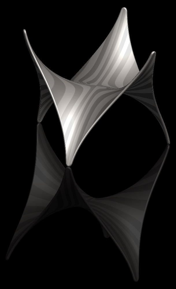
Hey Frank, take a look at this:
http://mathworld.wolfram.com/MonkeySaddle.html
At first I thought you could just plug in those parametric equations and generate the surface, but there's no way to do that that I could find. I ended up using several curve-by-equations and running a boundary blend through them. It turned out nice, but it's brute-force and not very robust, i.e. I'm not able to tweak all the curves simultaneously. This gives the general shape, but I think there's more going on with the actual table design-wise.
Doug, thoughts?

Nov 12, 2015
11:11 AM
- Mark as New
- Bookmark
- Subscribe
- Mute
- Subscribe to RSS Feed
- Permalink
- Notify Moderator
Nov 12, 2015
11:11 AM
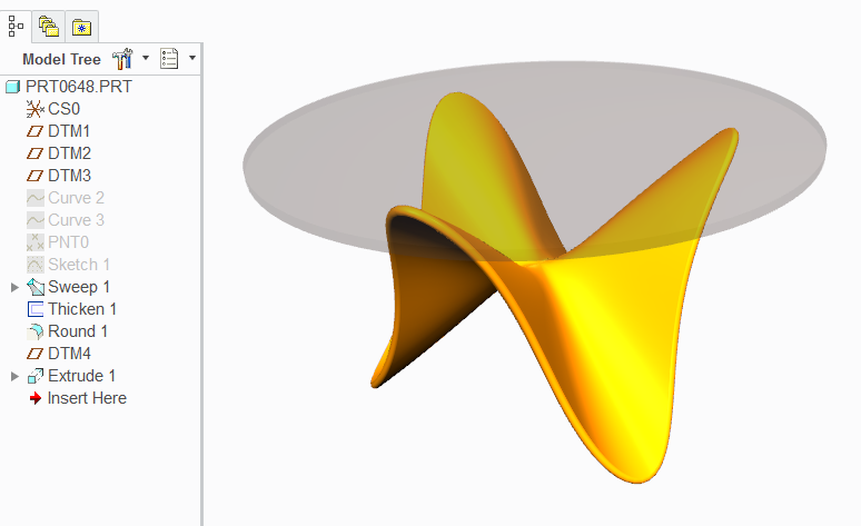
This was done using an equation curve and a sweep.
Nov 12, 2015
11:21 AM
- Mark as New
- Bookmark
- Subscribe
- Mute
- Subscribe to RSS Feed
- Permalink
- Notify Moderator
Nov 12, 2015
11:21 AM
Cool! Radially, those are line elements, right?
I thought about doing it as a VSS, but you can't make the curvature go to infinity or reverse itself.....unfortunately. that would be a GREAT enhancement!
Edit: Actually, this started as a simple Sw to Pro/E comparison.....and it looks like I've created a monster......but a COOL monster! Thanks Antonius, you've actually inspored me to make something like this.....but with different ends. Hmmmmm.....
Nov 12, 2015
11:29 AM
- Mark as New
- Bookmark
- Subscribe
- Mute
- Subscribe to RSS Feed
- Permalink
- Notify Moderator
Nov 12, 2015
11:29 AM
It can be done with VSS since it is just Z that reverses ...and the girdling of cylindrical radius can be manipulated too.
If nothing else, for the edges and use them for a another sweep.
The object in general is fascinating only that it is a hexagon that was melted and stretched.
You never know how the forming die was made.
And no, in section, they are not linear. It is a controlled spline.
Nov 12, 2015
12:45 PM
- Mark as New
- Bookmark
- Subscribe
- Mute
- Subscribe to RSS Feed
- Permalink
- Notify Moderator
Nov 12, 2015
12:45 PM
I actually just found a way in a test part to do it with a VSS, AND get nice curvature in the direction I want. I got the "S" curve in the section to go from one direction, flatten out, and then reverse itself as it revolves around Z (up in the pic). It'll be an interesting take on the Monkey Saddle, difference being in the tips (...just the tip!).
Yeah, without the actual part in front of us, you can never model it "exactly", and it's just one persons educated guess vs. another's, but just knowing HOW to do something like that is fun and educational. I learned a few new things so I'm happy!
I wonder how it was actually made? I'm guessing cast. Maybe a bug flat hexagon of wax, heated up, bent that way, and then covered in sand?
Nov 12, 2015
01:11 PM
- Mark as New
- Bookmark
- Subscribe
- Mute
- Subscribe to RSS Feed
- Permalink
- Notify Moderator
Nov 12, 2015
01:11 PM
My guess is vacuum formed.
Nov 12, 2015
01:23 PM
- Mark as New
- Bookmark
- Subscribe
- Mute
- Subscribe to RSS Feed
- Permalink
- Notify Moderator
Nov 12, 2015
01:23 PM
You mean with one of these??? 
After all, Mr. Dyson says it's the BombDiggity!!!!
Nov 13, 2015
01:34 PM
- Mark as New
- Bookmark
- Subscribe
- Mute
- Subscribe to RSS Feed
- Permalink
- Notify Moderator
Nov 13, 2015
01:34 PM
Well, anything made in SW DOES suck....just sayin'.....
Nov 12, 2015
02:09 PM
- Mark as New
- Bookmark
- Subscribe
- Mute
- Subscribe to RSS Feed
- Permalink
- Notify Moderator
Nov 12, 2015
02:09 PM
Really? Something that big? Interesting. I'd love to see it in person. Actually, I think I have, I'll have to go back to the store and see if that's what I remember seeing.
Nov 12, 2015
11:15 AM
- Mark as New
- Bookmark
- Subscribe
- Mute
- Subscribe to RSS Feed
- Permalink
- Notify Moderator
Nov 12, 2015
11:15 AM
Looks nice! I didn't know what that was, I'll have to check out the link, thanks!
I did it with simple curves, and a couple cuts. I haven't tweaked it, but it should be robust.
Yours looks like pretty much the same thing, except for the tips are more like the table. Which, if I'd not put the tip rounds on, it would look more like.
It's a fun shape though, right?
Edit: Holy moley, those equations made my head hurt! glad I can do it without those! 
Nov 12, 2015
11:50 AM
- Mark as New
- Bookmark
- Subscribe
- Mute
- Subscribe to RSS Feed
- Permalink
- Notify Moderator
Nov 12, 2015
11:50 AM
Not to be a Stickler...but, while cool...it's nowhere near the actual product in the photo. There is much, much more to that form than a string of equations can create. Okay, okay...it's all a string of equations....but you know what I mean. That form has some concavity and inflections that cannot be replicated with "one" feature.
Nov 12, 2015
11:58 AM
- Mark as New
- Bookmark
- Subscribe
- Mute
- Subscribe to RSS Feed
- Permalink
- Notify Moderator
Nov 12, 2015
11:58 AM
When equations fail, we have evalgraph() Where is evalgraph() in SW, Frank?
Nov 12, 2015
12:36 PM
- Mark as New
- Bookmark
- Subscribe
- Mute
- Subscribe to RSS Feed
- Permalink
- Notify Moderator
Nov 12, 2015
12:36 PM
Well, I'll certainly be looking for it in SW! IF it exists (doubt it) and I find it, I'll let ya know!
Nov 12, 2015
12:58 PM
- Mark as New
- Bookmark
- Subscribe
- Mute
- Subscribe to RSS Feed
- Permalink
- Notify Moderator
Nov 12, 2015
12:58 PM
Comedians...the lot of you! 
Nov 12, 2015
01:41 PM
- Mark as New
- Bookmark
- Subscribe
- Mute
- Subscribe to RSS Feed
- Permalink
- Notify Moderator
