
Turn on suggestions
Auto-suggest helps you quickly narrow down your search results by suggesting possible matches as you type.
Showing results for
Turn on suggestions
Auto-suggest helps you quickly narrow down your search results by suggesting possible matches as you type.
Showing results for
Community Tip - Learn all about the Community Ranking System, a fun gamification element of the PTC Community. X
- Community
- Creo+ and Creo Parametric
- 3D Part & Assembly Design
- Use whole wrapped sketch as trimming object on sur...
Options
- Subscribe to RSS Feed
- Mark Topic as New
- Mark Topic as Read
- Float this Topic for Current User
- Bookmark
- Subscribe
- Mute
- Printer Friendly Page
Use whole wrapped sketch as trimming object on surface
Apr 09, 2013
02:32 PM
- Mark as New
- Bookmark
- Subscribe
- Mute
- Subscribe to RSS Feed
- Permalink
- Notify Moderator
Apr 09, 2013
02:32 PM
Use whole wrapped sketch as trimming object on surface
Hi modellers!
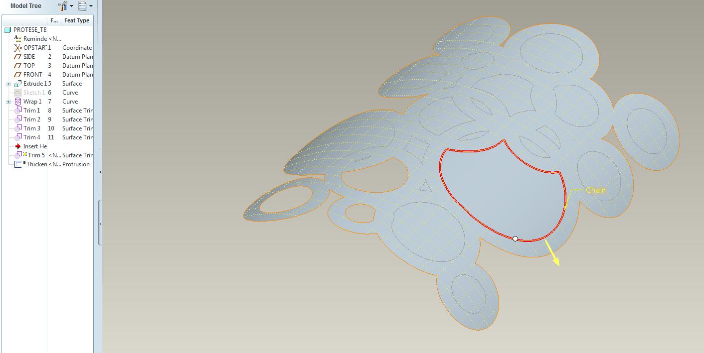
I have a sketch (imported from illustrator) that I've have wrapped onto a curved surface.
Now I want to use the wrapped sketch to trim the surface.
The problem is the fact that I'm only allowed to pick one outline for each trim. This means that I have to really many trims to get the surface I want.
Is there any way to do this proces more efficiently and speed up the proces?
I want all the centers of the circles cut out, like the three in the lower left corner.
Best regards.
27 REPLIES 27
Apr 09, 2013
02:53 PM
- Mark as New
- Bookmark
- Subscribe
- Mute
- Subscribe to RSS Feed
- Permalink
- Notify Moderator
Apr 09, 2013
02:53 PM
In some cases, you can project those curves back to flat plane sketch and then extrude that sketch to remove material. In your case, this would work easily as the curved surface is less than 90 degrees.
Apr 09, 2013
03:14 PM
- Mark as New
- Bookmark
- Subscribe
- Mute
- Subscribe to RSS Feed
- Permalink
- Notify Moderator
Apr 09, 2013
03:14 PM
Query-select the curve and see if it won't let you select the ENTIRE curve (composed of all of them). If not, as Nike says, Just do It. 
Apr 09, 2013
06:09 PM
- Mark as New
- Bookmark
- Subscribe
- Mute
- Subscribe to RSS Feed
- Permalink
- Notify Moderator
Apr 09, 2013
06:09 PM
PTC isn't listening to Nike... You can only select a single closed loop in the trim tool. You get the option to select the Rule-based "All curves in feature" but it won't allow selection of a wrapped sketch with multiple closed loops.
On the other hand, you can extrude a thin feature and remove material, which, of course, has to be planar. I see room for improvement here 
Apr 09, 2013
06:26 PM
- Mark as New
- Bookmark
- Subscribe
- Mute
- Subscribe to RSS Feed
- Permalink
- Notify Moderator
Apr 09, 2013
06:26 PM
Yeah, wasn't sure, I'd not come across that with the multiple loops. You'd THINK you could select the whole feature, but nooooooooo......
Apr 09, 2013
06:35 PM
- Mark as New
- Bookmark
- Subscribe
- Mute
- Subscribe to RSS Feed
- Permalink
- Notify Moderator
Apr 09, 2013
06:35 PM
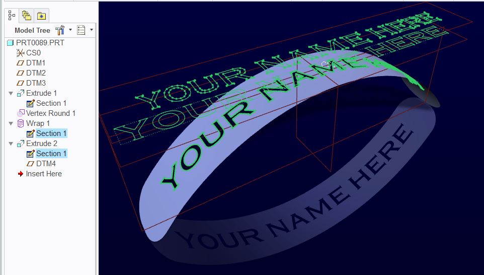
 Yep. Ran into this when doing text.
This is probably more telling:
You can select the loop of each letter when you Project the curves from the Wrap feature back to the sketch plane (when creating the Extrude sketch). This makes it a very simple process. Remember to extrude as a thin feature since solids and surfaces don't mix.
Apr 10, 2013
01:56 AM
- Mark as New
- Bookmark
- Subscribe
- Mute
- Subscribe to RSS Feed
- Permalink
- Notify Moderator
Apr 10, 2013
01:56 AM
Thank you for your answers both of you
I manage to solve the problem by projecting the wrap back to the sketch plane and extrude the holes away.
If you have a surface that bend more than 180 degrees, you have to do it the hard way?
Thanks again.
Apr 10, 2013
03:29 AM
- Mark as New
- Bookmark
- Subscribe
- Mute
- Subscribe to RSS Feed
- Permalink
- Notify Moderator
Apr 10, 2013
03:29 AM
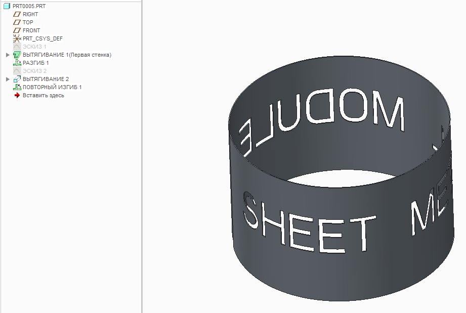
You can also use Sheet Metal Module for this purpose.
Apr 10, 2013
09:47 AM
- Mark as New
- Bookmark
- Subscribe
- Mute
- Subscribe to RSS Feed
- Permalink
- Notify Moderator
Apr 10, 2013
09:47 AM
Yes, the hard way would be to make 2, or better yet, 3 orientations for the extrude, but you might need to pick a direction from the inside so it doesn't intersect the "far wall".
Nice work, Valdimir!
Apr 10, 2013
10:38 AM
- Mark as New
- Bookmark
- Subscribe
- Mute
- Subscribe to RSS Feed
- Permalink
- Notify Moderator
Apr 10, 2013
10:38 AM
Why not project it onto a flat surface, cut your quilt, do a spinal bend, and then thicken the surface?
Apr 10, 2013
10:45 AM
- Mark as New
- Bookmark
- Subscribe
- Mute
- Subscribe to RSS Feed
- Permalink
- Notify Moderator
Apr 10, 2013
10:45 AM
I was waiting for that one.
You have to be careful with spinal bend not to scale the part along the bend contour.
If the surface was not one that lends itself to a "wrap", it would be a great choice.
Apr 10, 2013
01:10 PM
- Mark as New
- Bookmark
- Subscribe
- Mute
- Subscribe to RSS Feed
- Permalink
- Notify Moderator
Apr 10, 2013
01:10 PM
Who, ME???
For the one he wanted, it seemed like it would work fairly well. It'd be interesting to do 2 on top of each other and see if there was any distortion.
I've found that the intersection of 2 curves is NOT exact in creo anymore, so if that curve is crucial, use a curve from the intersection of 2 surfaces. Dunno why there's the discrepancy now.......
Yeah, in Pro/E, there's a dozen ways to skin a cat (and sometimes you have to try ALL of them to find one that actually works...... ).....
Apr 10, 2013
01:32 PM
- Mark as New
- Bookmark
- Subscribe
- Mute
- Subscribe to RSS Feed
- Permalink
- Notify Moderator
Apr 10, 2013
01:32 PM
I've found that the intersection of 2 curves is NOT exact in creo anymore, so if that curve is crucial, use a curve from the intersection of 2 surfaces. Dunno why there's the discrepancy now.......
Yes it is. Sketch 2 curves; select them both, and click "intersect". Poof! ...new 3D curve.
Apr 10, 2013
02:00 PM
- Mark as New
- Bookmark
- Subscribe
- Mute
- Subscribe to RSS Feed
- Permalink
- Notify Moderator
Apr 10, 2013
02:00 PM
I've had some issues with it lately, not being an exact intersection. I was trying to do a boundary blend and it wasn't working (blahblahblah does not form a loop blahblahblah....). It was causing me trouble until I really looked, and say there was a slight issue. I did an intersection of 2 surfaces and it worked.
The wiring harness I did using the intersection of 2 curves, but it didn't need to be as exact. Hmmm......
Apr 10, 2013
02:17 PM
- Mark as New
- Bookmark
- Subscribe
- Mute
- Subscribe to RSS Feed
- Permalink
- Notify Moderator
Apr 10, 2013
02:17 PM
That must be that "relative accuracy" where close is close enough ...and sometimes better 
Apr 10, 2013
03:51 PM
- Mark as New
- Bookmark
- Subscribe
- Mute
- Subscribe to RSS Feed
- Permalink
- Notify Moderator
Apr 10, 2013
03:51 PM
....or usually not good enough!
Apr 10, 2013
01:34 PM
- Mark as New
- Bookmark
- Subscribe
- Mute
- Subscribe to RSS Feed
- Permalink
- Notify Moderator
Apr 10, 2013
01:34 PM
...
Yeah, in Pro/E, there's a dozen ways to skin a cat (and sometimes you have to try ALL of them to find one that actually works......
So does trying those other 11 methods first count in the reduced mouseclick directive? 
Apr 15, 2013
08:58 AM
- Mark as New
- Bookmark
- Subscribe
- Mute
- Subscribe to RSS Feed
- Permalink
- Notify Moderator
Apr 15, 2013
08:58 AM
Antonius Dirriwachter wrote:
So does trying those other 11 methods first count in the reduced mouseclick directive?
I think that's been superseded by the "must have ribbon" directive. 
Apr 11, 2013
01:49 AM
- Mark as New
- Bookmark
- Subscribe
- Mute
- Subscribe to RSS Feed
- Permalink
- Notify Moderator
Apr 11, 2013
01:49 AM
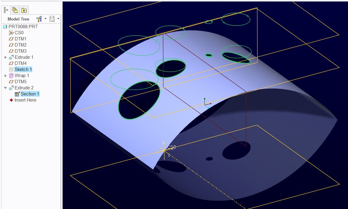
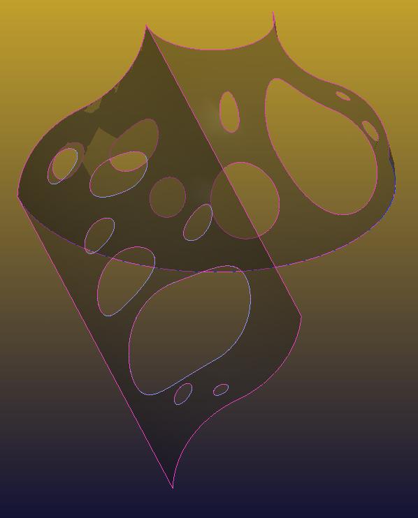
Actually the screenshot was of a simplified problem.
What I actually need, is to cut the holes in a double curved surface. I don't think that sheetmetal and spinal bend would help me here. Maybe? Otherwise it's a great way to do it.Thanks for the suggestions.
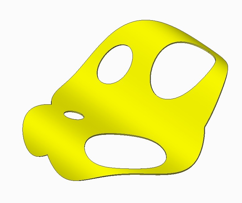
I manage to solve it by extruding the wrapped sketch that was projected back on a workplane... and because you can't wrap a sketch onto a double curved surface I had to create a single curved "dummy" surface that immitated the double curved surface as close as possible.
The result:
It's still just a test and not the final part.
Thank you very much for your help. You just helped me gain some new CAD skills
Apr 11, 2013
02:22 AM
- Mark as New
- Bookmark
- Subscribe
- Mute
- Subscribe to RSS Feed
- Permalink
- Notify Moderator
Apr 11, 2013
02:22 AM
Indeed, that does become work. What is the manufacturing process for the part? Is it thermo-formed plastic or coined metal where it starts out flat when the holes are punched/cut?
You might try a sheetmetal part using a form-feature. That module can do some amazing things with adding holes on curved surfaces and managing deformation. I haven't found a way to unfold that as a metal part but you can lift a surface from it and flatten that to check what you start out with when you get the sheetmetal part done.
Apr 11, 2013
02:26 AM
- Mark as New
- Bookmark
- Subscribe
- Mute
- Subscribe to RSS Feed
- Permalink
- Notify Moderator
Apr 11, 2013
02:26 AM
All right. Will take a look at form-feature.
It's planned to be 3dprinted. The quantity is only 1 and it gives me alot more freedom regarding the geometry.
Apr 11, 2013
10:46 AM
- Mark as New
- Bookmark
- Subscribe
- Mute
- Subscribe to RSS Feed
- Permalink
- Notify Moderator
Apr 11, 2013
10:46 AM
I think what Antonius is getting at is how is it going to be manufactured in the real world? This will determine exactly how you'll need to model it to account for the method and any material stretching (as in sheetmetal or formed sheet plastic - I guarantee your holes will NOT be round). If it's going to be an injection molded plastic part, simply use a projected cut and draft the edges, because that's the way the mold will be made.
If this is just some fantasy part for fun and never being actually made, do you really need to wrap anything or are you just doing it for fun? Hell, simply extrude the holes thru it normal to the back plane and be done with it unless you need or want anything else.
I'm thinking of a method you might be able to use for a wrap on a compound-curved surface, but it'll most likely require a couple steps.
Apr 11, 2013
11:49 AM
- Mark as New
- Bookmark
- Subscribe
- Mute
- Subscribe to RSS Feed
- Permalink
- Notify Moderator
Apr 11, 2013
11:49 AM
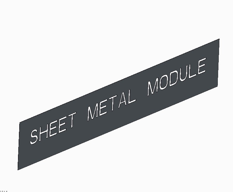
Just for fun, I wrapped a series of circles onto a "developable" surface thas has curvature normal to the exis of the final part. So, the circumference of the circles is correct (unlike projected). then I did a spinal bend on it to get the compound curvature (like a revolved surface). As you can see, now the holes are distorted near the top (smaller end) where the spinal bend actually shrunk the material. I wrote a relation to force the developed length to be equal to the big end. I could easily have donw it the other way with the relations to make the holes near the top undistorted and have the material stretch (as would more normally be the case) to distort the bottom. But, this was quick and easy. Note: This is sort of cheating to create a Toroidial bend, with greater flexibility. I later thickened it and it worked at 1" thick no problem!
For you though, what I'd suggest is simply punching holes thru a surface, normal to a point on the surface corresponding to where the axis of the hole goes thru, then thickening the surface. This will give you distortion of the walls of the holes, based on the thickness. This will most likely give you geometry most closely matched to a real world production process.
Apr 11, 2013
02:20 PM
- Mark as New
- Bookmark
- Subscribe
- Mute
- Subscribe to RSS Feed
- Permalink
- Notify Moderator
Apr 11, 2013
02:20 PM
Very nice! That's one I'll have to remember.
If the holes are more or less random, you could also Project a sketch normal to the face. The sketch would be the distorted feature that would closely approximate the position and round shape. In the sketch, the corresponding hole would be an ellipse. The closer you need it to be, the more the sketch plane will need to be normal to the surface at the hole's axis. I think that Sheetmetal holes will do this but controlling their location is enigmatic. But it is the most accurate I can think of as it does map the hole with K-factors in mind.
Yet, I think you, Esben, have already done a marvelous job on your part. So the correct answer is "NO" ...there is no easier way.
Apr 11, 2013
02:43 PM
- Mark as New
- Bookmark
- Subscribe
- Mute
- Subscribe to RSS Feed
- Permalink
- Notify Moderator
Apr 11, 2013
02:43 PM
Thanks! I never thought to try and do that with a spinal bend. They teach you spinal bends for planar parts, but I thought, why not? It seemed to work just fine!. And, I think it ends up giving you something you couldn't get with a toriodial bend. I'm sure I can find a use for this somewhere.....
Yeah, it looks like he's got a model that will work. I can't speak the the sheetmetal thing since I don't use that module.
Apr 12, 2013
02:02 AM
- Mark as New
- Bookmark
- Subscribe
- Mute
- Subscribe to RSS Feed
- Permalink
- Notify Moderator
Apr 12, 2013
02:02 AM
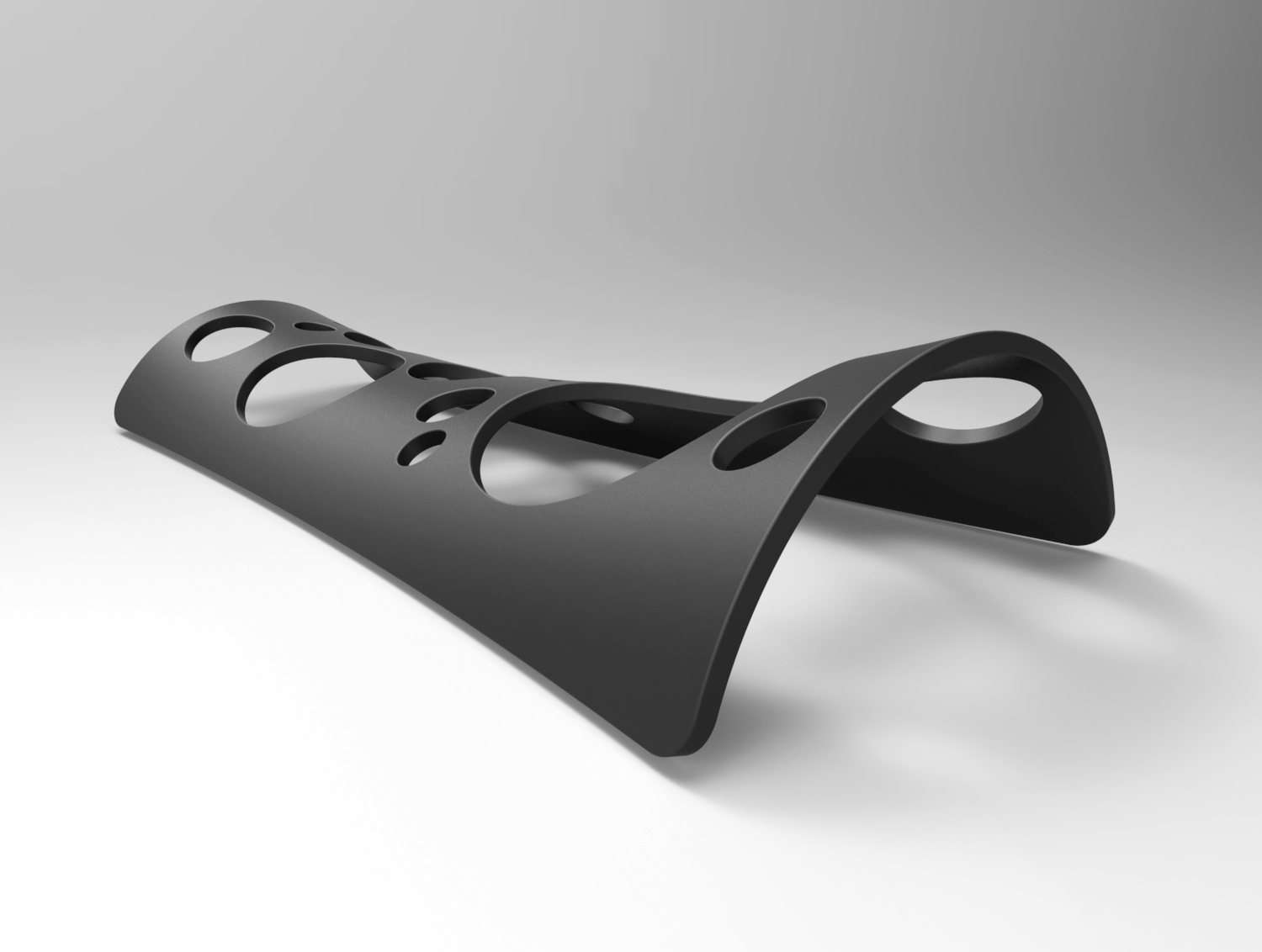
: 3dprint is going to be used as the manufacturing process in the real world. With the rather complex geometri (a lot of details will be added to the surface) that I need to be as precise as possible, and the fact that I only need one single piece, I think 3dprint is going to be the most suitable manufactoring proces.
I need to wrap it as much as possible, because I don't want the pattern to be stretched. The pattern is probably going to be more complex and not just simple circles. It was just for testing.
Unfortunatly I don't think I can use the spinal bend method as I need the double curved surface to be quite precise. I think it's easier to get an excact shape with a boundary blend tool compared to a spinal bend.
@Antonius: All right. I also think I got what I needed.
Again, both of you, thank you for your help. It's much appreciated.
Apr 12, 2013
03:05 PM
- Mark as New
- Bookmark
- Subscribe
- Mute
- Subscribe to RSS Feed
- Permalink
- Notify Moderator
Apr 12, 2013
03:05 PM
Well, it looks like you got it then. The pic looks good.
Apr 12, 2013
03:33 PM
- Mark as New
- Bookmark
- Subscribe
- Mute
- Subscribe to RSS Feed
- Permalink
- Notify Moderator
Apr 12, 2013
03:33 PM
I can only offer one other tip. You could map a special grid in your favorite graphics software that accounts for the distortion. You could even do the core map in Creo.
Apply a decal of what you want the end result to look like.
You would create a distorted X-Y grid. Basically sectioning the part equally along the "cylinder" and lengthwise (polar divided equally along the afore created arcs). Now use the analysis "measure lengths" to lay out the grid.
Now you have a map of what the part is flat without fabrication distortion.
Use this as an underlay for making an image to use as a decal. Next, you will likely have to deform the image to map it correctly using the parametric application of the decal. You will probably need perspective stretch capabilities.
Once applied, you have an underlay for creating the feature using sketches and extrudes/trims.
In short, it is like making an accurate map to wrap onto a globe which is tougher than it looks. It is a bit of work but my just help with the precision you are after.
