Community Tip - You can Bookmark boards, posts or articles that you'd like to access again easily! X
- Community
- Creo+ and Creo Parametric
- Manufacturing (CAM)
- Re: How to model a helical sweep cut that matches ...
- Subscribe to RSS Feed
- Mark Topic as New
- Mark Topic as Read
- Float this Topic for Current User
- Bookmark
- Subscribe
- Mute
- Printer Friendly Page
How to model a helical sweep cut that matches a CNC tool path?
- Mark as New
- Bookmark
- Subscribe
- Mute
- Subscribe to RSS Feed
- Permalink
- Notify Moderator
How to model a helical sweep cut that matches a CNC tool path?
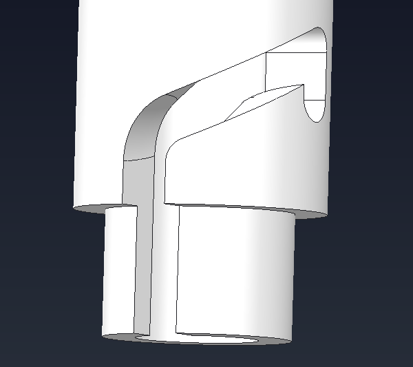
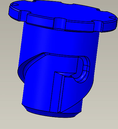
I've been trying to model a locking feature that utilizes a keyway that is on a cylindrical surface. The keyway starts as a vertical cut then goes into an angle then dips down to lock a pin in place on a mating part. I've been trying to use a Helical Sweep, but the cut that it provides does not stay normal to the cylindrical surface, it forms a curved bottom surface, even though my cross section is rectangular. I'm trying to get the keyway to mimic the path that would be cut using a 4-axis CNC milling machine. Can anyone help?

This thread is inactive and closed by the PTC Community Management Team. If you would like to provide a reply and re-open this thread, please notify the moderator and reference the thread. You may also use "Start a topic" button to ask a new question. Please be sure to include what version of the PTC product you are using so another community member knowledgeable about your version may be able to assist.
- Labels:
-
General
- Mark as New
- Bookmark
- Subscribe
- Mute
- Subscribe to RSS Feed
- Permalink
- Notify Moderator
It is very difficult to get Creo to accurately capture what a cutter really does as it moves through a part. Take a look at these two discussions:
- Mark as New
- Bookmark
- Subscribe
- Mute
- Subscribe to RSS Feed
- Permalink
- Notify Moderator
I agree Tom, this problem has hit me about 3 times over the years. I typically don't work on parts like these since I'm a big dumb welded steel guy. Solid body sweep is the best terminology that is needed (as mentioned in one of your links). And trying to get someone to understand why the model is not correct, man, that can be a real pain too. I was wondering if Dan had stole the part he was doing from my coworker which was the last time I hacked on the problem. We ended up with a "reasonable" solution but I don't think they used our model for machining. It wasn't exactly perfect but would have been fully functional for our purposes.

- Mark as New
- Bookmark
- Subscribe
- Mute
- Subscribe to RSS Feed
- Permalink
- Notify Moderator
Dan,
I have been working with several cylinder cams over the past several months. What I found works best (minimizes the chance of distortion) is to create sketches and curves to match the center line of the cam path (for helical curves it is easiest to use a "curve from equation" and generate you equation in cylindrical coordinates). As long as the endpoints are coincident, you should be able to select all of the curve parts as part of a sweep. Then, it is just a matter of making sure that the sweep is set to stay Normal to Surface. Afterwords, you can add in radii where needed along the path.
- Mark as New
- Bookmark
- Subscribe
- Mute
- Subscribe to RSS Feed
- Permalink
- Notify Moderator
Creo doesn't get it right. It' doesn't capture the effect of the leading and trailing edges of the cutter, only the on-axis profile. See the barrel cam discussion for lots of pictures of this.


