- Community
- Creo+ and Creo Parametric
- Manufacturing (CAM)
- Manufacturing a part with multiple operations on a...
- Subscribe to RSS Feed
- Mark Topic as New
- Mark Topic as Read
- Float this Topic for Current User
- Bookmark
- Subscribe
- Mute
- Printer Friendly Page
Manufacturing a part with multiple operations on a 4-axis milling machine.
- Mark as New
- Bookmark
- Subscribe
- Mute
- Subscribe to RSS Feed
- Permalink
- Notify Moderator
Manufacturing a part with multiple operations on a 4-axis milling machine.
Hi
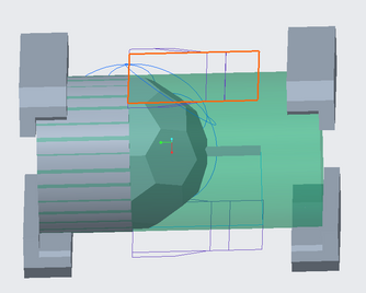
So for my masterthesis I currently am testing the possibilities and restrictions with a 4-axis milling machine (Roland MDX-50 with a rotational A-axis). I am now trying to mill a football (or soccerball, I'll just call it "Ball" from now on) as you can see in the image below. Normally we do this on a 5-axis machine, but the goal is to see if the MDX-50 can realise this piece and how precise it will be.

I already made some volume roughs (with a 6mm End Mill) and profiling steps (with a 2mm Ball Mill) on the top- and the bottom side. So it will look like this:
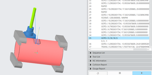
So I currently have 2 Coordinate Systems (further abbreviated as "CS"), 1 on the top and 1 on the bottom half. I used each CS to define an Operation. I can select both operations and ask to perform the Remove Material Simulation (as visible in Image 2). The simulation will do as I ask, but between the 2 operations, the tool will "teleport" from one place to another, because the second operation uses a different CS and an other clearance plane (of course).
However when I want to run it on my machine, the tool will not be able to perform this "teleportation". I previously tackled this problem by manually editing the G-code. (I used G54 for CS 1 and G55 for CS2. Then after post-processing I added the line "G90 G55 G21" where the second operation started and I made sure to manually add a "A180."-line to make sure the part was rotated 180degrees first because CS2 was on the bottom half of the part.)
So when it is just 2 operations this is doable, but when there are many more operations, with not so easy to calculate angles for the A-axis, this will become very hard.
So my question is: How can I combine my 2 operations on a 4-axis milling machine so that Creo calculates at what angle the A-axis should stand so I won't have to manually edit my G-code.
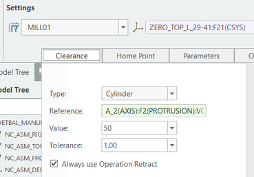
For anyone wondering, yes I changed my Work Center to a 4-axis machine that rotates around the A axis and my Operations have a Cylindrical Clearance (See 2 images below).
I hope someone can help me solve this problem.
If you need more information, just let me know and I'll try to let you know ASAP.
Excuse me for my not so great English and thank you in advance.
- Mark as New
- Bookmark
- Subscribe
- Mute
- Subscribe to RSS Feed
- Permalink
- Notify Moderator
If it were me, I would probably use some CL Commands at the end of the G54 based operation or the beginning of the G55 based operation, to move the tool away from the part and to a "safe" position for the transition to from G54 to G55. It's kind of like doing the manual editing, but you are actually defining tool motions, and they will always be included in your output files automatically.
Adding these kinds of commands is possible in at least a couple of ways I know of:
(1) Editing the toolpath in the last sequence to add the commands.
(2) Defining an Auxiliary sequence that just does the added CL commands.
I generally prefer the second choice, because it's then really obvious to me in the future, just what I did to get the tool safely from one place to another.
Also, I do a LOT of playing the toolpath to verify I didn't create a disaster.
- Mark as New
- Bookmark
- Subscribe
- Mute
- Subscribe to RSS Feed
- Permalink
- Notify Moderator
Hey KenFarley
So I am still trying what you said to do by just adding CL Commands.
Sadly, it does not yet go as planned. I regularly get "Fatal Errors" when trying to verify the tool paths using the simulation.
This is how I am currently trying to add the CL commands:
In the last sequence of my first operation I press CL Command and add a "GOTO"-command. I then input the following:
X, Y and Z-coördinates represent a safe position, away from the part so it could rotate without any collisions. I, J and K should represent that the tool has been rotated 180degrees. (0, 1, 0 and 0, -1, 0 should then represent angles of 90 and 270degrees.) (If I am not mistaken the $-sign is just there for readability (just like the "/n" in Python to create a new line).
So when I try to run it, this happens (I skipped some of the early steps just to show the new CL command):
As you can see, the transistion from line 34 to 35 is too abruptly. I also am not 100% sure I gave it the correct coordinates now. Because IF the tool would stay in the upper left corner and then we would let the A-axis turn 180degrees. The tool would still have to be in that same corner (but now it looks like it would stick with it's tooltip under the part instead of above it).
So I wanted to first make it seem less abruptly. So I added the command below, before the previously created "GOTO"-command.
By doing this the machine should first go to these coördinates without rotating (I, J and K are all 0). When arrived it can rotate 180 degrees
(I,J,K = 0, 0, -1).
However, this is the result:
I have not sent the traceback to Technical Support.
I wanted to ask you first how you do it, because clearly this isn't the right way.
I hope you can show me a little example of you using a custom CL command.
Would you use the "GOTO" or rather the "ROTATE" command?
I now used the GOTO-command because in a previous project Creo automatically used the GOTO, so I figured that it would be possible like that.
I hope you can help me further once again.
Thanks in Advance!
- Mark as New
- Bookmark
- Subscribe
- Mute
- Subscribe to RSS Feed
- Permalink
- Notify Moderator
I've not done such CL command insertion in a 4-axis program, but have done it a lot in 3-axis. The concept behind it is I'm telling the tool where I want it to go, in the sequence of motions I want. So, for this set of motions, I'd be trying to tell the machine how to:
(1) Move the tool along the Z axis, upwards, far enough to clear the part(s) in a safe manner.
(2) Move the tool to the starting position for the next operation.
For such motions I usually use either the "Goto Point" or "Go Delta" commands. You can't assume the program is going to do anything safely, that's why I explicitly tell it to move only in Z to get clear of the part and then give it the necessary X and Y coordinates to go to.
For 4-axis work, I'd have to figure out what is needed to get to the necessary "side" of the part for the next operation. Is it a ROTATE or ROTABL from the CL commands? I'm not sure. You can check out the output of "regular" toolpaths in the Creo-generated ".ncl" file and see what the commands there are saying, or look up the syntax of the NCL code. Maybe you'll need to do the move in a series of points, or maybe the ROTABL does it all in one go. You'll have to experiment with it to verify.
- Mark as New
- Bookmark
- Subscribe
- Mute
- Subscribe to RSS Feed
- Permalink
- Notify Moderator
There are many ways to approach this problem- this is what I do.
Use only one operation for the machining you are describing.
Set a "machine coordinate" system based on your machine tool and fixturing. This will be the only coordinate system used to generate CL files, and, ultimately, the g-code. It could theoretically be anywhere, but the post is going to expect it to be on the center-line of the 4th axis. The axes should be parallel with the XYZ axes of the machine tool. The position along the rotating axis can be anywhere that is convenient. Your A axis will coincide with the X axis.
Set individual "sequence coordinate" systems based on the sequences you write. There can be as many as you need, Their main purpose is to set the tool orientation for each sequence. The z axis of the sequence defines the orientation of the tool axis in relation to the machine coordinate system. Mill windows, clearance planes, etc, will be defined by the sequence coordinates. The CL file will be composed of xyz positions and ijk tool vectors based on the machine coordinate system. You will need to make sure you have a post set up to give you the expected output in g-code. Creo will output cylindrical clearance moves between positions provided you have used a cylindrical clearance type.
When programming like this, the closer your cnc controller fixture coordinate is to the physical 4th axis rotation center-line, the better your part will be. If things aren't lining up, suspect a problem with your fixture offset and adjust accordingly.
You can set individual coordinate systems for each sequence by changing the COORDINATE_OUTPUT to SEQUENCE_CSYS, and then have a different FIXT_OFFSET_REG for each sequence, but I avoid that when possible.
Although I can't tell for certain, it looks like you may be able to position the faces to profile mill each surface, then array around the axis instead of surface milling like you are currently.


