
Turn on suggestions
Auto-suggest helps you quickly narrow down your search results by suggesting possible matches as you type.
Showing results for
Turn on suggestions
Auto-suggest helps you quickly narrow down your search results by suggesting possible matches as you type.
Showing results for
- Community
- Creo+ and Creo Parametric
- Manufacturing (CAM)
- Did You Know? PTC Creo 3.0 Enhancements: Additive ...
Options
- Subscribe to RSS Feed
- Mark Topic as New
- Mark Topic as Read
- Float this Topic for Current User
- Bookmark
- Subscribe
- Mute
- Printer Friendly Page
Did You Know? PTC Creo 3.0 Enhancements: Additive Manufacturing (3D Printing)
Jun 24, 2015
10:06 AM
- Mark as New
- Bookmark
- Subscribe
- Mute
- Subscribe to RSS Feed
- Permalink
- Notify Moderator
Jun 24, 2015
10:06 AM
Did You Know? PTC Creo 3.0 Enhancements: Additive Manufacturing (3D Printing)
PTC Creo 3.0 M040 is paving the way for additive manufacturing (3D printing) with new features that simplify the design process. With PTC Creo 3.0 M040, users can create molds, tooling, manufacturing aids and actual production parts for additive manufacturing. In today’s post, Jose Coronado, CAD Product Manager, explains how to prepare, place, and analyze your model for additive manufacturing. He also covers additional features available with when using a Stratasys Connex printer:
Using PTC Creo 3.0 M040 users can design, validate, and print 3D parts. The preview of the model within the tray helps to reduce printing errors and productivity loss during the manufacturing process. To begin, select your 3D printer from the Printer drop down menu. Your printer’s tray should appear on the screen below your model. If you are using a Stratasys Connex printer, you have the option to select the material for your printed model within the system. Open the Material Setup window using the window expand icon next to the Printers and Materials button. Here, you can select the palette of materials and colors that you plan to use.
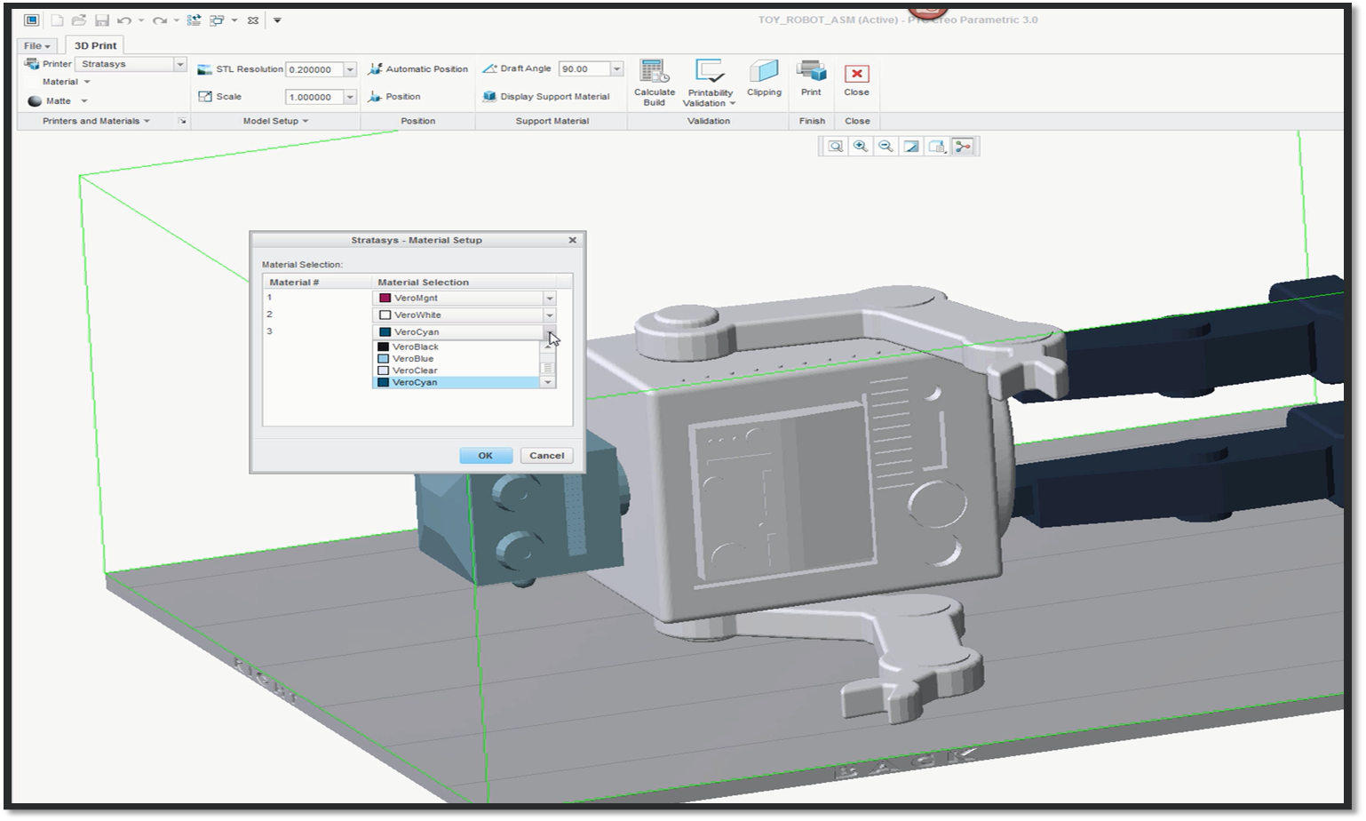
In this example, a Stratasys printer and three shades of Vero material are selected.
When using a Stratasys Connex printer, you can apply material and colors to each part of your assembly. Simply select a color from the Material drop down menu and use the paint brush to apply color to each component. Whether you are using a Stratasys Connex printer or another brand of 3D printer, you should change the resolution of the model using the STL Resolution drop down menu. Use the preset resolutions like Course, Medium, and Fine, to change the print quality. You can also enter a specific resolution by typing into the STL Resolution text box.
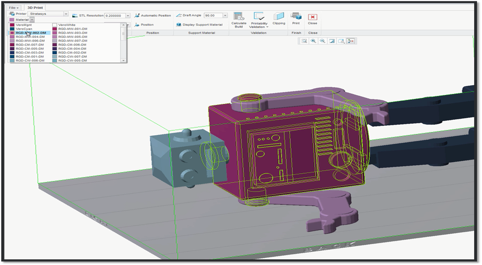
This robot model is composed of material with different shades of Cyan and Magenta and has an STL Resolution of 0.2.
The next step is to position the model on the tray and review the build and support material. If you are using a Stratasys Connex printer you can allow the system to place your model by using the Automatic Positioning feature. When using any other printer, you will have to manually position your model. To manually position the model select the Position feature and use the draggers. When using a Stratasys Connex printer you can also calculate the required amount of build and support material. Select the Display Support Material button to show the estimation of support material required for the build process. With any printer you can activate the Clipping feature and use the dragger to see where the build and support material will be used within the model. The support material is displayed for visualization purposes and is calculated using the draft angle specified by the user. Although it does not represent the real support structure that the printer will use, it does allow the user to see where the support material will likely touch the surfaces of the model. This is especially useful for situations where the user wants to prevent critical surfaces from being touched by a post-processing step, like polishing. Users can also use the Clipping feature to identify whether support material trapped inside closed or semi-closed volumes will be difficult to eliminate after printing.
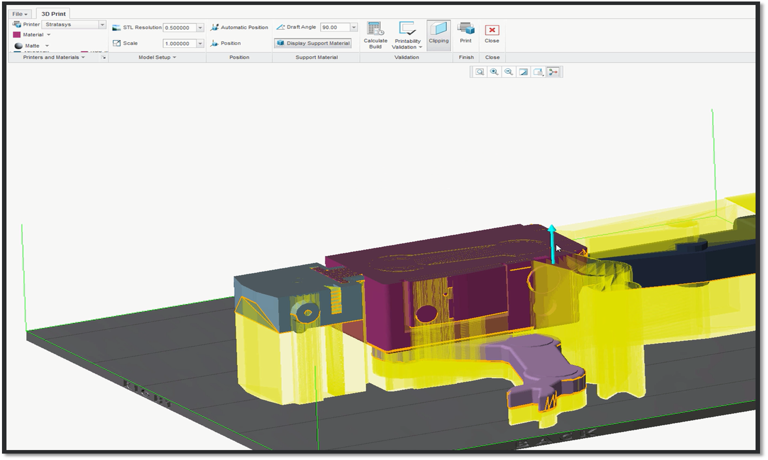
Here, we can see where the support material will appear for each layer of the robot.
Once you have finished preparing and placing your assembly, you can validate the printability of your model. Open the Printability Validation drop down menu and select one of the options: Validate All, Validate Narrow Gaps, or Validate Thin Walls. A separate window will open for you to select which parts of your assembly require validation. Once the validation is complete, the system will list the printability issues in a table. Click an issue in the table to zoom in for closer review. Once you are satisfied with your model, click the Print button to finish the process.
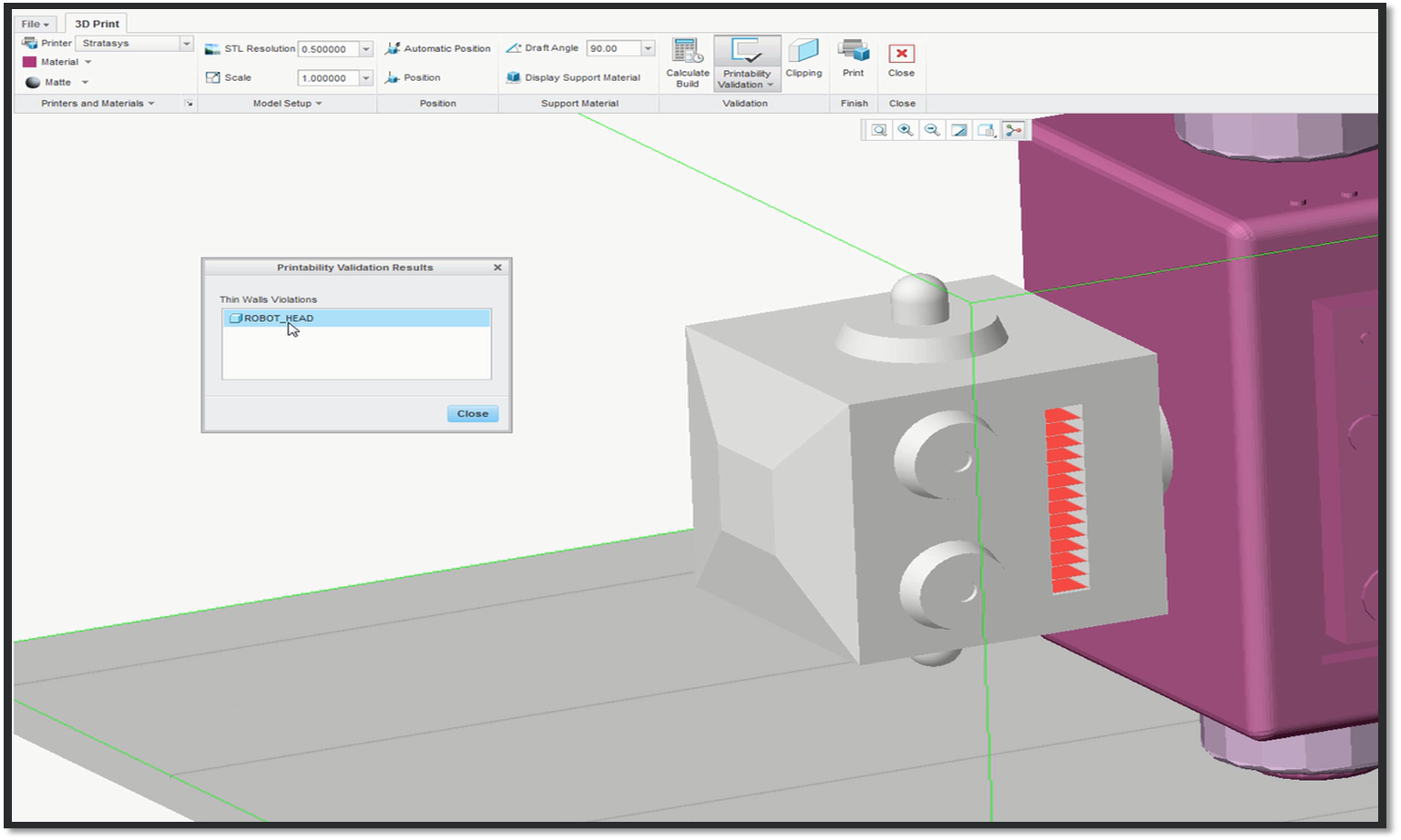
In this example, the robot head has a thin wall violation.
To learn more about Additive Manufacturing (3D Printing) in PTC Creo, click here.
Stay tuned to our “Did You Know” blog series as we cover all of the exciting, new enhancements in PTC Creo 3.0.
For more in-depth product feature explanations, visit our Tech Tips area.
Have some ideas about what PTC Creo product features you’d like to learn more about? Send me a message or leave a comment below and we’ll write up the best ideas from the community. Thanks for reading, looking forward to all of your feedback!
In case you missed it, check out our recent Did You Know posts covering PTC Creo 3.0 enhancements:
1) Fast Facts! Quick Tips for Using PTC Creo - Part Modeling Part 2
2) Did You Know? PTC Creo 3.0 Enhancements: 3D Thickness in PTC Creo Parametric
3) Did You Know? PTC Creo 3.0 Enhancements: Graphical Realism – Realistic Bump Mapping
This thread is inactive and closed by the PTC Community Management Team. If you would like to provide a reply and re-open this thread, please notify the moderator and reference the thread. You may also use "Start a topic" button to ask a new question. Please be sure to include what version of the PTC product you are using so another community member knowledgeable about your version may be able to assist.
0 REPLIES 0
Announcements
Top Tags
