
Turn on suggestions
Auto-suggest helps you quickly narrow down your search results by suggesting possible matches as you type.
Showing results for
Turn on suggestions
Auto-suggest helps you quickly narrow down your search results by suggesting possible matches as you type.
Showing results for
Community Tip - New to the community? Learn how to post a question and get help from PTC and industry experts! X
- Community
- PTC Education
- PTC Education Forum
- Arranging ‘loose’ parts for a natural looking rend...
Options
- Subscribe to RSS Feed
- Mark Topic as New
- Mark Topic as Read
- Float this Topic for Current User
- Bookmark
- Subscribe
- Mute
- Printer Friendly Page
Arranging ‘loose’ parts for a natural looking render
Jan 28, 2013
03:45 PM
- Mark as New
- Bookmark
- Subscribe
- Mute
- Subscribe to RSS Feed
- Permalink
- Notify Moderator
Jan 28, 2013
03:45 PM
Arranging ‘loose’ parts for a natural looking render
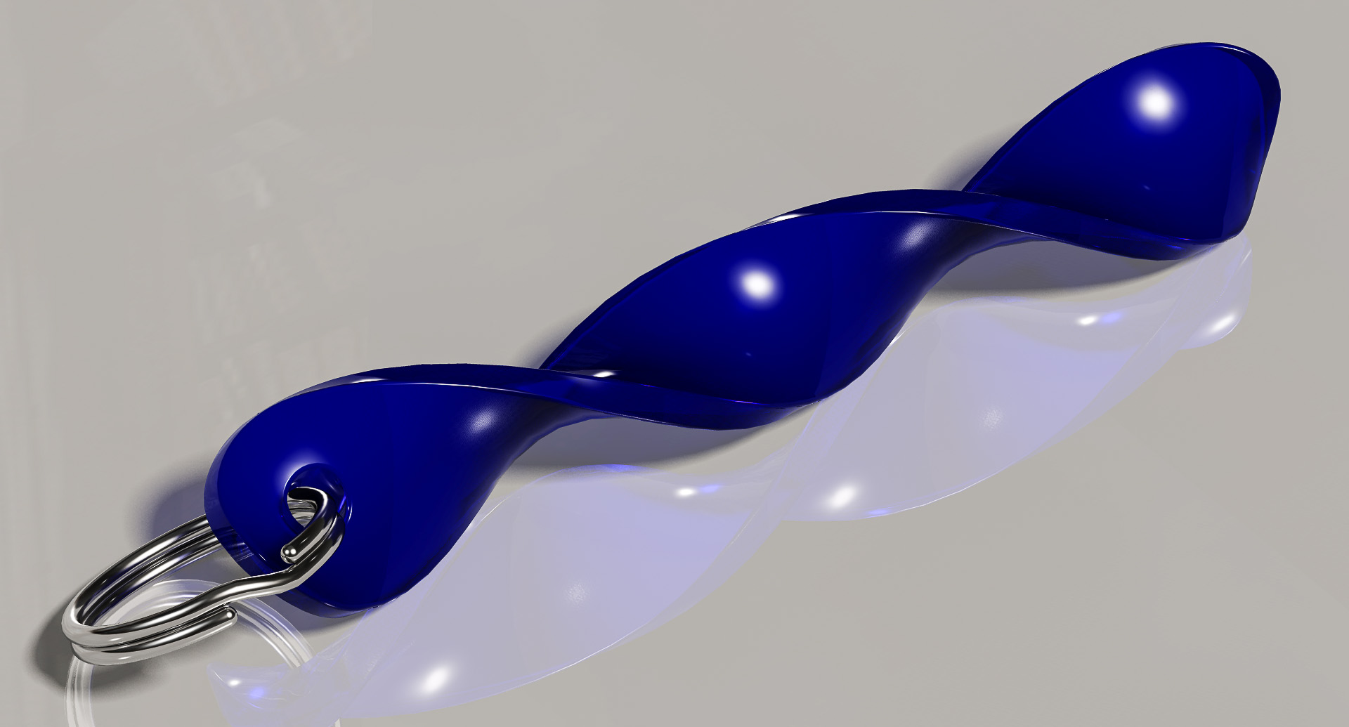
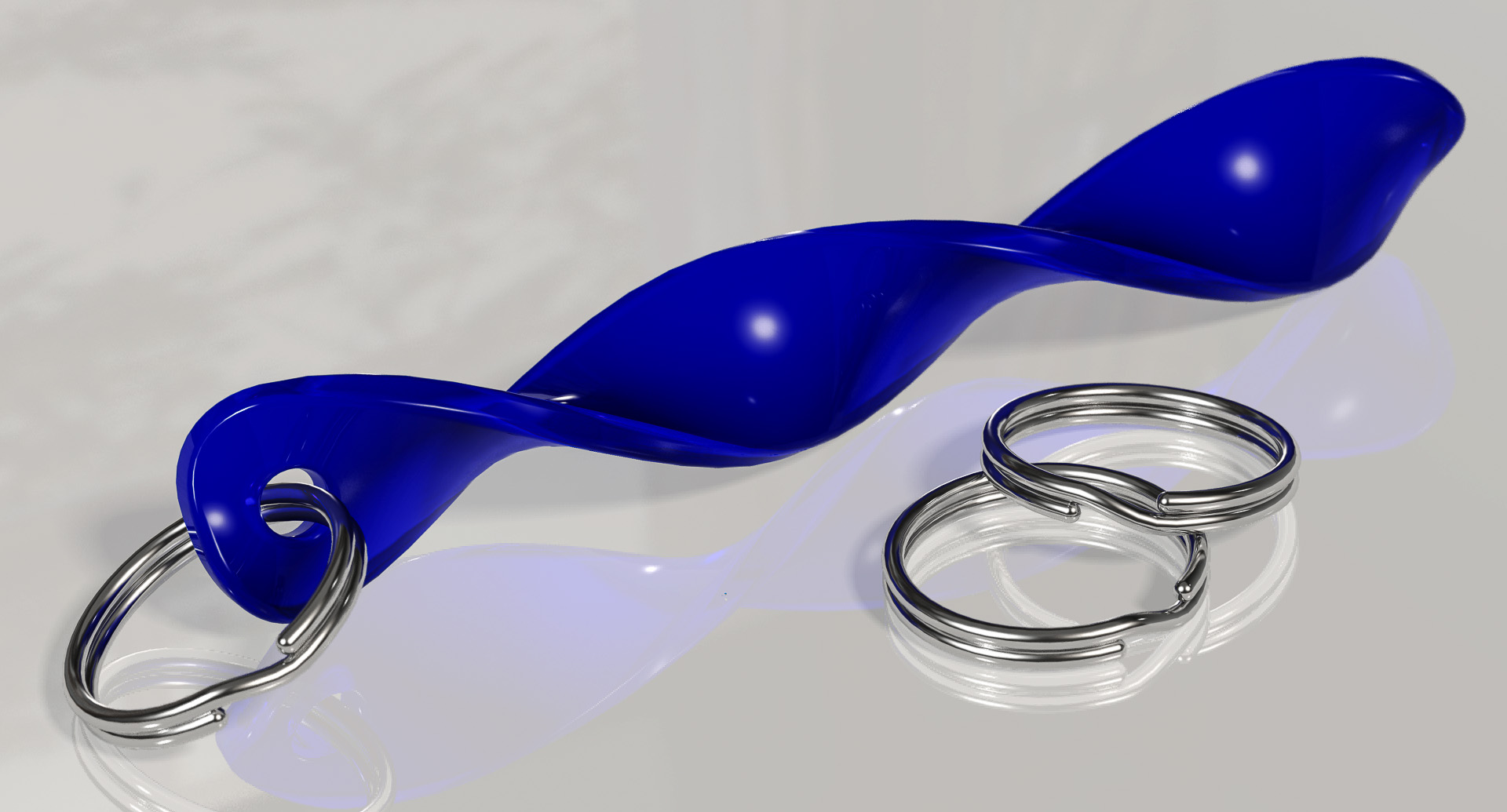
A little test for myself to see if I could bring two skills together, the twist and the sweep, into something useful.
I’m OK with the render but it took far, far too long to just get everything on the ‘floor’ and the ring through the hole without interference; done, pretty much, by eye and a lot of fiddling around in Parametric. Even then I had to force a slightly unnatural alignment between the components to simplify adjustments. More than two or three elements would drive me insane.
Am I missing something obvious here? A tool or approach that would make this sort of assembly easier? Any tips?
Solved! Go to Solution.
1 ACCEPTED SOLUTION
Accepted Solutions
Feb 09, 2013
01:00 PM
- Mark as New
- Bookmark
- Subscribe
- Mute
- Subscribe to RSS Feed
- Permalink
- Notify Moderator
Feb 09, 2013
01:00 PM
I was probably recalling the previous render.
Use draft render while you are setting everything up.
There is one chain link fence showing the plane that is in focus. Get this in position first.
Then slowly increase the Blur value until you get the effect you want and use Maximum quality for the final image.
5 REPLIES 5
Jan 29, 2013
04:22 AM
- Mark as New
- Bookmark
- Subscribe
- Mute
- Subscribe to RSS Feed
- Permalink
- Notify Moderator
Jan 29, 2013
04:22 AM
Tony, Are you using the floor provided in Render? You could create a floor 'part' in the assembly and use constraints like tangent to make the twist and split-ring touch the floor exactly. Datum points in the hole and in the split ring might also let you align them easier.
Getting the render exactly how you want it to look can take longer than modelling the parts! Understanding the theory of light and photography can also help. Did you see the depth of field option?
It looks like you already rounded sharp edges. Perfect edges are a give-away the image is a CAD render. Autoround is useful here as it does all edges in one feature.
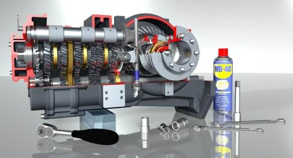
Adding context can also increase the realism. The image below is from our demo catalogue and uses the WD40 can and tools to add context to the gearbox.
Great work!
Feb 03, 2013
09:09 AM
- Mark as New
- Bookmark
- Subscribe
- Mute
- Subscribe to RSS Feed
- Permalink
- Notify Moderator
Feb 03, 2013
09:09 AM
Latest effort above... an improvment? Quicker to produce, for sure.
Certainly creating a “floor part” simplifies things in so many ways – even when I’m just arranging by eye. Though my quick and dirty way of losing the ‘floor’ is just to make it really, really small in the final render – I’m sure there’s a better way.
Can’t believe I hadn’t used Datum Points BTW ( hangs head in shame 🙂
The tangent constraint is still something of a mixed blessing; sometimes working fine and other times rearranging the assembly in unexpected, even radical, ways... and especially annoying when I get a major shift when I click to accept the assembly of a part. I’m sure you’ve set me off in the right direction though - much appreciated.
I’d seen the DoF option existed but I’m actually quite enjoying the ‘hyper-real’ effect I’m getting from the renderer – just for the novelty at the minute perhaps. I’m sure you know better than I do that ‘depth of field’ is a widely and easily misunderstood concept – even amongst photographers who *have* to deal with it all the time – I tried it out a little in this render but I’ll be sure to give it a proper go next time I have to produce a print.
Feb 04, 2013
12:25 PM
- Mark as New
- Bookmark
- Subscribe
- Mute
- Subscribe to RSS Feed
- Permalink
- Notify Moderator
Feb 04, 2013
12:25 PM
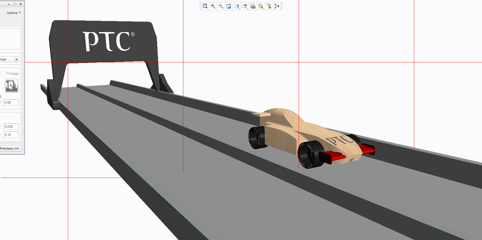
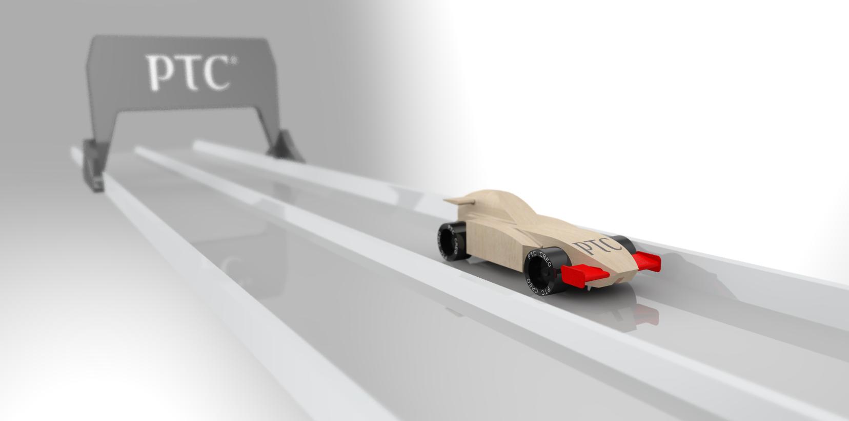
I dabble in photography (club night tonight!) but prefer what I call the "chain link fences" in Creo. Anything between the two grids is in focus, anything in front of the nearest grid and behind the furthest grid is out of focus. I can definitely see the effect in your render. It might work better looking along the twist so there is maximum difference in distance between the closest and furthest bit of the model.
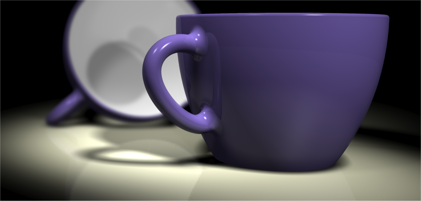
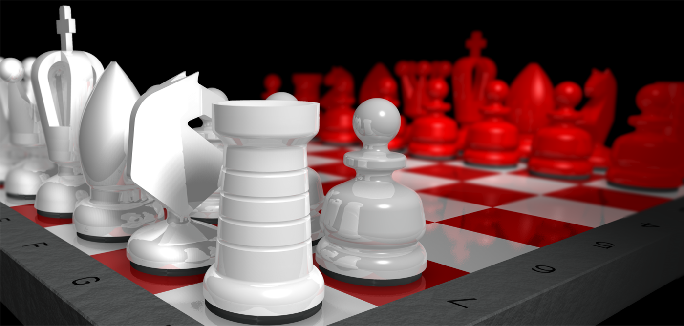
Below are a couple of images showing depth of field created by a PTC application engineer.
Feb 08, 2013
05:58 PM
- Mark as New
- Bookmark
- Subscribe
- Mute
- Subscribe to RSS Feed
- Permalink
- Notify Moderator
Feb 08, 2013
05:58 PM
All my blathers about DoF was really just trying to say DoF is a property of a print (and viewer), not a capture.
But I can see how effective it is to have some very ‘clearly’ out of focus background objects to add context; I really do like the “Cups” composition you put up.
I can’t manage to find two ‘Chain link fences’ though – just the one “Focus” distance wheel and a “Blur” slider in Scenes/Effects.
Feb 09, 2013
01:00 PM
- Mark as New
- Bookmark
- Subscribe
- Mute
- Subscribe to RSS Feed
- Permalink
- Notify Moderator
Feb 09, 2013
01:00 PM
I was probably recalling the previous render.
Use draft render while you are setting everything up.
There is one chain link fence showing the plane that is in focus. Get this in position first.
Then slowly increase the Blur value until you get the effect you want and use Maximum quality for the final image.
