
Turn on suggestions
Auto-suggest helps you quickly narrow down your search results by suggesting possible matches as you type.
Showing results for
Turn on suggestions
Auto-suggest helps you quickly narrow down your search results by suggesting possible matches as you type.
Showing results for
Community Tip - You can Bookmark boards, posts or articles that you'd like to access again easily! X
- Community
- PTC Education
- PTC Education Forum
- How to connect multiple pin constraints
Options
- Subscribe to RSS Feed
- Mark Topic as New
- Mark Topic as Read
- Float this Topic for Current User
- Bookmark
- Subscribe
- Mute
- Printer Friendly Page
How to connect multiple pin constraints
Oct 10, 2013
11:18 PM
- Mark as New
- Bookmark
- Subscribe
- Mute
- Subscribe to RSS Feed
- Permalink
- Notify Moderator
Oct 10, 2013
11:18 PM
How to connect multiple pin constraints
You guys have been a great deal of help to our team so far. Thank You!
We do have another issue that I'm unsure how to resolve.
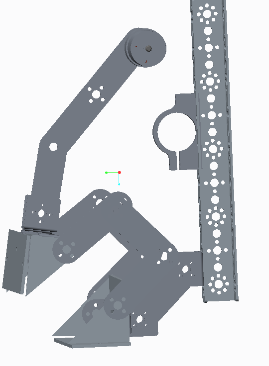

We created this claw, and have pin joints between in the following areas. Everything looks like it will work perfectly, I just cannot figure out how to connect the motor back to the motor housing, since I've already constrained it to the arm. Is there a different way to constrain the pieces so they will form a complete loop?
Solved! Go to Solution.
1 ACCEPTED SOLUTION
Accepted Solutions
Oct 15, 2013
01:31 PM
- Mark as New
- Bookmark
- Subscribe
- Mute
- Subscribe to RSS Feed
- Permalink
- Notify Moderator
Oct 15, 2013
01:31 PM
For anyone else following this thread, Ryan shared his models with me and we found the few issues that were preventing the model from connecting as a mechanism.
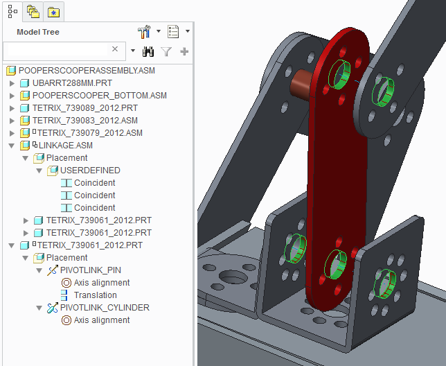
In Ryan's model, there are two moving elements, the top arm of the scooper and the motor and linkage that will drive it. We took the linkage out of the top assembly, created a subassembly with the two fixed links and assembled it directly to the motor which already has a PIN connection defined in it. That gave us an assembly with two independently moving subassemblies that needed to be connected with the final link.
The final link was created with two constraint sets; one PIN and one CYLINDER. The PIN connection is at the top and the CYLINDER connection is at the bottom. The PIN connection defines the position and motion while the CYLINDER connection is only there for motion.
5 REPLIES 5
Oct 11, 2013
03:03 AM
- Mark as New
- Bookmark
- Subscribe
- Mute
- Subscribe to RSS Feed
- Permalink
- Notify Moderator
Oct 11, 2013
03:03 AM
Hi Ryan,
One of the keys to making a mechanism work properly is to assemble it like you would in real life.
1. Would you normally connect that arm to the motor first?
2. How does that arm really connect to the motor?
Oct 11, 2013
09:54 AM
- Mark as New
- Bookmark
- Subscribe
- Mute
- Subscribe to RSS Feed
- Permalink
- Notify Moderator
Oct 11, 2013
09:54 AM
Ryan,
Looking at the images, you need to assemble the motor in a fixed location first. Then connect all the moving pieces second. In fact, if you already have pin joints where all the arrows are, you just need to put the motor in the motor clamp and you should be good-to-go. I'm guessing you may have assembled the motor to the linkage? in that case, remove the contstraint set, create a new one to mount it in the clamp and then add a second constraint set to the linkage. It will need (2) constraint sets. A pin join for each connection at the ends.
If you have a Windchill project, ZIP up your design and upload it as a new document. Then invite me to the project as "-" and I can take a look at it. I'll be hiking, apple picking and pumpkin carving for the weekend, but back on Monday afternoon.
Oct 11, 2013
11:33 PM
- Mark as New
- Bookmark
- Subscribe
- Mute
- Subscribe to RSS Feed
- Permalink
- Notify Moderator
Oct 11, 2013
11:33 PM
Scott,
I tried all options you recommended, and am at a loss. I emailed you the file (sorry, haven't had time to figure out Windchill yet), and will welcome any and all help you can offer.
Thanks so much!
Ryan
Oct 15, 2013
01:31 PM
- Mark as New
- Bookmark
- Subscribe
- Mute
- Subscribe to RSS Feed
- Permalink
- Notify Moderator
Oct 15, 2013
01:31 PM
For anyone else following this thread, Ryan shared his models with me and we found the few issues that were preventing the model from connecting as a mechanism.
In Ryan's model, there are two moving elements, the top arm of the scooper and the motor and linkage that will drive it. We took the linkage out of the top assembly, created a subassembly with the two fixed links and assembled it directly to the motor which already has a PIN connection defined in it. That gave us an assembly with two independently moving subassemblies that needed to be connected with the final link.
The final link was created with two constraint sets; one PIN and one CYLINDER. The PIN connection is at the top and the CYLINDER connection is at the bottom. The PIN connection defines the position and motion while the CYLINDER connection is only there for motion.
Oct 15, 2013
11:50 PM
- Mark as New
- Bookmark
- Subscribe
- Mute
- Subscribe to RSS Feed
- Permalink
- Notify Moderator
Oct 15, 2013
11:50 PM
I've got to hand it to Scott, and the rest of the PTC team! These guys went above and beyond to answer my questions, and educate me further in the CREO software.
Thanks a TON!!!!
