- Community
- PTC Education
- PTC Education Forum
- Re: Distance and Coincident constraints in specifi...
- Subscribe to RSS Feed
- Mark Topic as New
- Mark Topic as Read
- Float this Topic for Current User
- Bookmark
- Subscribe
- Mute
- Printer Friendly Page
Distance and Coincident constraints in specific dimensions
- Mark as New
- Bookmark
- Subscribe
- Mute
- Subscribe to RSS Feed
- Permalink
- Notify Moderator
Distance and Coincident constraints in specific dimensions
I need to align a circular object relative to an axis and two planes. I need it to be certain distances off of each of the two planes, but otherwise on axis. In other words, I need it to be a coincident constraint in the X-Y plain ONLY, while it is two independent distance constraints in the X-Z and Y-Z planes. The axis is moving vertically and horizontally as the design evolves, so simply setting things manually via other flat surfaces is insufficient.
Is there a way to specify a specific dimension for coincident restraints in general? Or is there a good way to accomplish this in specific?
Solved! Go to Solution.
Accepted Solutions
- Mark as New
- Bookmark
- Subscribe
- Mute
- Subscribe to RSS Feed
- Permalink
- Notify Moderator
I think you have several methods to do this depending on your preferences.
You could create a single part and define all your locations with sketched lines, datum points, axes and planes. This would basically be a skeleton model...especially useful for creating a real assembly later.
You could create a couple of basic objects (Table, Mirror, etc.) and place them in an assembly. Again, create axes, points and datums for positioning.
Hope this helps.
-Josh
- Mark as New
- Bookmark
- Subscribe
- Mute
- Subscribe to RSS Feed
- Permalink
- Notify Moderator
Hi Elliot,
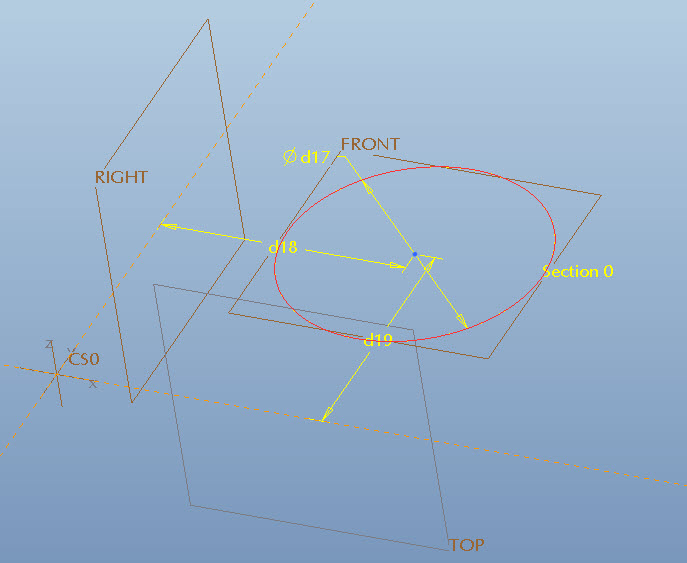
I'm having a difficult time understanding what you are trying to express. The figure below is just a sketch on the XY plane. d18 and d19 are completely independant. The circle is on the XY plane, but that can be changed by making a new plane offset from XY. There is a theoretical axis through the center, but you can just as easily create a new axis in that location where the circle is defined as going through it.
- Mark as New
- Bookmark
- Subscribe
- Mute
- Subscribe to RSS Feed
- Permalink
- Notify Moderator
What figure? i think you forgot the attachment.
- Mark as New
- Bookmark
- Subscribe
- Mute
- Subscribe to RSS Feed
- Permalink
- Notify Moderator
Hmm, sorry about that, it showed up when I posted ![]()

- Mark as New
- Bookmark
- Subscribe
- Mute
- Subscribe to RSS Feed
- Permalink
- Notify Moderator
OK let me describe the system. It's too crowded or I would post an image.
I have a mirror mounted at 45degrees a distance above a table, and m bouncing a light beam off it. It is hanging from other things above it so the height is not fixed relative to the table. 2 imaging optics are placed along the beam path for collimation and focusing. These optics are attached to the table, so they need to be a certain distance above the table. I have put 2 45degree rotated axes through the mirror for the light path. I need the lenses to be Coincident ONLY in terms of staying on center with the optic axis in the horizontal. I need the lens height to stay fixed (the distance from the mirror is set by optical table hole spacing, but is independent in any case).
- Mark as New
- Bookmark
- Subscribe
- Mute
- Subscribe to RSS Feed
- Permalink
- Notify Moderator
I think you have several methods to do this depending on your preferences.
You could create a single part and define all your locations with sketched lines, datum points, axes and planes. This would basically be a skeleton model...especially useful for creating a real assembly later.
You could create a couple of basic objects (Table, Mirror, etc.) and place them in an assembly. Again, create axes, points and datums for positioning.
Hope this helps.
-Josh
- Mark as New
- Bookmark
- Subscribe
- Mute
- Subscribe to RSS Feed
- Permalink
- Notify Moderator
My head started spinning about 1/2 way through the explanations. By constraints do you mean assembly or sketch (assuming assembly here)?
I am also going to suggest what Joshua suggested... build a "skeleton" of sorts to represent the final goal.
Since you probably want the final coincident focus, you might also consider looking at it from a "reverse engineering" perspective when doing the assemblies.


