
Turn on suggestions
Auto-suggest helps you quickly narrow down your search results by suggesting possible matches as you type.
Showing results for
Turn on suggestions
Auto-suggest helps you quickly narrow down your search results by suggesting possible matches as you type.
Showing results for
Community Tip - Did you get called away in the middle of writing a post? Don't worry you can find your unfinished post later in the Drafts section of your profile page. X
Options
- Subscribe to RSS Feed
- Mark Topic as New
- Mark Topic as Read
- Float this Topic for Current User
- Bookmark
- Subscribe
- Mute
- Printer Friendly Page
How to solve a RC circuit, including piecewise and periodic functions in time domain?
Aug 01, 2016
12:11 PM
- Mark as New
- Bookmark
- Subscribe
- Mute
- Subscribe to RSS Feed
- Permalink
- Notify Moderator
Aug 01, 2016
12:11 PM
How to solve a RC circuit, including piecewise and periodic functions in time domain?
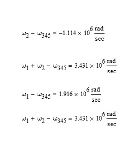
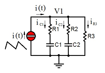
Hi All, I have a circuit like this, where I want the components value R1,C1,R2,C3 and R3 as the user inputs.
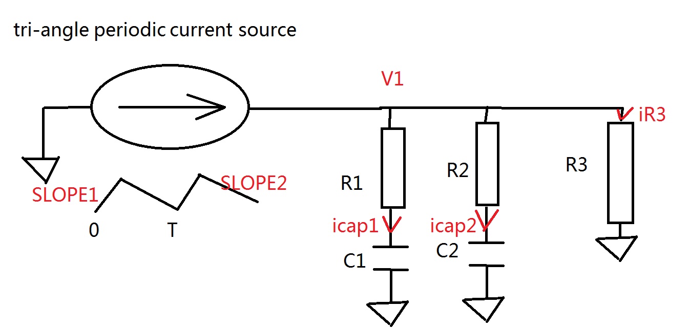
I can list the equations to solve this circuit, but I do not know how to realize it in Mathcad. Would anybody help me?
I have attached the worksheet. In addition, if this circuit can be solved, can we also add a control button, to "trigger" the Mathcad calculation by clicking it?
Thank you!
Solved! Go to Solution.
Labels:
- Labels:
-
Physics
1 ACCEPTED SOLUTION
Accepted Solutions
Aug 01, 2016
05:13 PM
- Mark as New
- Bookmark
- Subscribe
- Mute
- Subscribe to RSS Feed
- Permalink
- Notify Moderator
Aug 01, 2016
05:13 PM
I would analyze the circuit as follows (a little rushed and without comments):

29 REPLIES 29
Aug 01, 2016
02:08 PM
- Mark as New
- Bookmark
- Subscribe
- Mute
- Subscribe to RSS Feed
- Permalink
- Notify Moderator
Aug 01, 2016
02:08 PM
Hi.
If you have the symbolic solution, can use this definition for Isource, which can be differentiated and integrated symbolically.
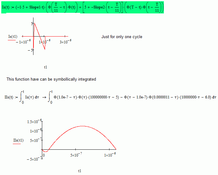
If you want the numeric solution must to write an odesolve block with the functions that you have write, and your periodic function works for the block. But need to write in therms of the variable t, so, integration variable must to be tau or something else, and t goes at the top limit of integration: I don't understand why you put T, the period there.
About a push button to make the calculus, mathcad usually don't need that: it recalc every time that something changes in the screen area.
Best regards.
Alvaro.
Aug 01, 2016
03:39 PM
- Mark as New
- Bookmark
- Subscribe
- Mute
- Subscribe to RSS Feed
- Permalink
- Notify Moderator
Aug 01, 2016
03:39 PM
Hi Alvaro, thank you for your advise! I have revised my code according to your advise, but I still cannot figure out how to solve the variables symbolically. Would you directly edit from my attached file? Thank you!
Aug 01, 2016
05:41 PM
- Mark as New
- Bookmark
- Subscribe
- Mute
- Subscribe to RSS Feed
- Permalink
- Notify Moderator
Aug 01, 2016
05:41 PM
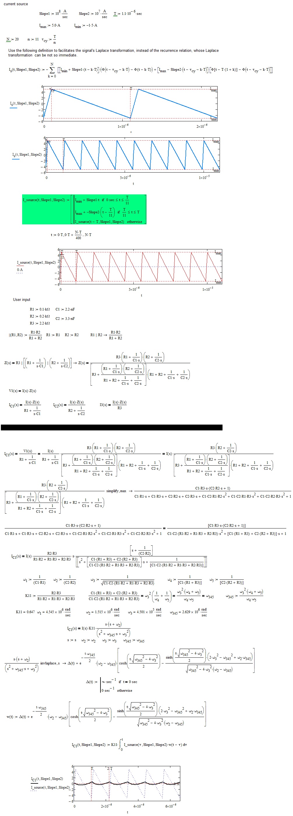
Hi. Attached, the odesolve block, trying to resolve the integral equations to differentials. But can't make it to work with odesolve. Maybe another one collab can see why.
Notice also that for t=0, it's wrong to assume i1, etc equals zero. Maybe you can translate the Is to make it zero to t=0.
Symbolic solution attached to, but it's useless.
Best regards.
Alvaro.
Aug 01, 2016
05:13 PM
- Mark as New
- Bookmark
- Subscribe
- Mute
- Subscribe to RSS Feed
- Permalink
- Notify Moderator
Aug 01, 2016
05:13 PM
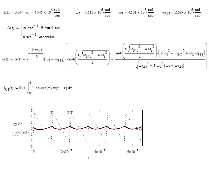
I would analyze the circuit as follows (a little rushed and without comments):
Aug 01, 2016
05:49 PM
- Mark as New
- Bookmark
- Subscribe
- Mute
- Subscribe to RSS Feed
- Permalink
- Notify Moderator
Aug 01, 2016
05:49 PM
Hi F.M., thank you so much for your detailed solution! I have the questions of three calculated/defined variables, would you advise?
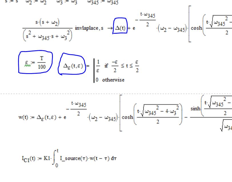
(1) what is the DELTA(t) provided by inverse laplace?
(2) what is the epsilon you defined?
(3) what is the theory in defining delta_epsilon(t) to replace delta (t)?
Thank you!
Aug 02, 2016
02:48 AM
- Mark as New
- Bookmark
- Subscribe
- Mute
- Subscribe to RSS Feed
- Permalink
- Notify Moderator
Aug 02, 2016
02:48 AM
Hallo yhuang-3,
the delta is the Dirac impulse. It is an impulse defined in the origin (t = 0), of infinite amplitude and unit area. The analytical definition, approximated and simpler, is the one I provided, but there are many others. You get it to the limit, for epsilon approaching zero. The topic is covered on all texts on calculus. The Dirac delta is commonly used in physics as well as in electrical engineering. I did the approximation of the Dirac pulse, only to draw the graph. Indeed, the approximation is not necessary. Better to use the definition of the Dirac pulse, as you can see in the following image.
In laboratory practice, you have to be very attentive to the voltage and current pulses. They can destroy the user systems and measuring instruments. The classic case is the output of a differentiator when the input is a square wave signal. The output that is obtained is a train of destructive pulses.
In your problem, being the impulses integrated, there is no production of pulses.
Greetings
FM
Aug 02, 2016
11:53 AM
- Mark as New
- Bookmark
- Subscribe
- Mute
- Subscribe to RSS Feed
- Permalink
- Notify Moderator
Aug 02, 2016
11:53 AM
What is saying F.M. is very important, and interesting.
First, the impulse, the delta "function", isn't a function, it is a "distribution", which is a limit of a succession of functions. That's why mathcad have not a numerical procedure to evaluate it: it isn't one. What F.M. shows is an usual approximation to the impulse, but if it don't work, can use other. Eventually, no one could represent the distribution, and need to work directly in this other domain.
Second, the concept that derivatives circuits can cause some accidents, like burn some component because the unitary impulse, which is a common error in the laboratory, and, unfortunately, in the industry too, but integral circuits are very stable. Is amazing the relationship between those physical elements, and the analytical derivative and integral: while the diff is a punctual function, and then unstable because depends only on the around of only one point, despite about what happen at any other, the integral depends of the entire interval, and then it is very stable Actually, in calculus can prove that it is continuous by the right.
Best regards.
Alvaro.
Aug 02, 2016
08:56 AM
- Mark as New
- Bookmark
- Subscribe
- Mute
- Subscribe to RSS Feed
- Permalink
- Notify Moderator
Aug 02, 2016
08:56 AM
A little suggestion to avoid copy and paste when defining the functions:

If I_source would be defined without if/otherwise using the Heaviside function Phi, I guess that I.C2 could be calculated symbolically (using Delta, w/o Delta_eps) )which would speed up the following plotting.
Werner
Aug 02, 2016
09:07 AM
- Mark as New
- Bookmark
- Subscribe
- Mute
- Subscribe to RSS Feed
- Permalink
- Notify Moderator
Aug 02, 2016
09:07 AM
Thank you, Werner for your feedback. But in Mathcad 15 we can use just the definition of Dirac pulse. While in previous Mathcd's versions, it seems to me, it was not possible, so, by habit, I also used in the latter case the approximation.
Greetings
FM
Aug 02, 2016
09:32 AM
- Mark as New
- Bookmark
- Subscribe
- Mute
- Subscribe to RSS Feed
- Permalink
- Notify Moderator
Aug 02, 2016
09:32 AM
> But in Mathcad 15 we can use just the definition of Dirac pulse.
? Not exactly sure what you mean by that?
The Dirac function is only available for symbolic calculation, also in MC15. It will fail when you try to evaluate it numerically, e.g. for plotting.
You created the function w2(t) and others by manually copying the results of the symbolic invlaplace operation and editing so your approx Delta is used. This is cumbersome and failure prone. So the main idea of my suggestion was to show that its possible to automate that procedure using the substitute command so no manual copying and editing is necessary anymore.
Concerning my last comment I had in mind to integrate symbolically (only possible if I_source uses no conditionals) as the integral of Dirac is Heavisides step and this function Phi is available for numeric evaluation, too. So the symbolically derived function would plot a lot quicker. But I haven't tried it myself and so I am not sure if this would work as expected. Furthermore you would have to find a different method to make the function periodically (nor sure if t <- mod(t,T) would work in combination with symbolic integration). Chances are that other modifications would be necessary, too, if you go that way. Not sure if its worth the effort.
Werner
Aug 02, 2016
10:47 AM
- Mark as New
- Bookmark
- Subscribe
- Mute
- Subscribe to RSS Feed
- Permalink
- Notify Moderator
Aug 02, 2016
10:47 AM
See below...
Aug 02, 2016
09:57 AM
- Mark as New
- Bookmark
- Subscribe
- Mute
- Subscribe to RSS Feed
- Permalink
- Notify Moderator
Aug 02, 2016
10:14 AM
- Mark as New
- Bookmark
- Subscribe
- Mute
- Subscribe to RSS Feed
- Permalink
- Notify Moderator
Aug 02, 2016
10:14 AM
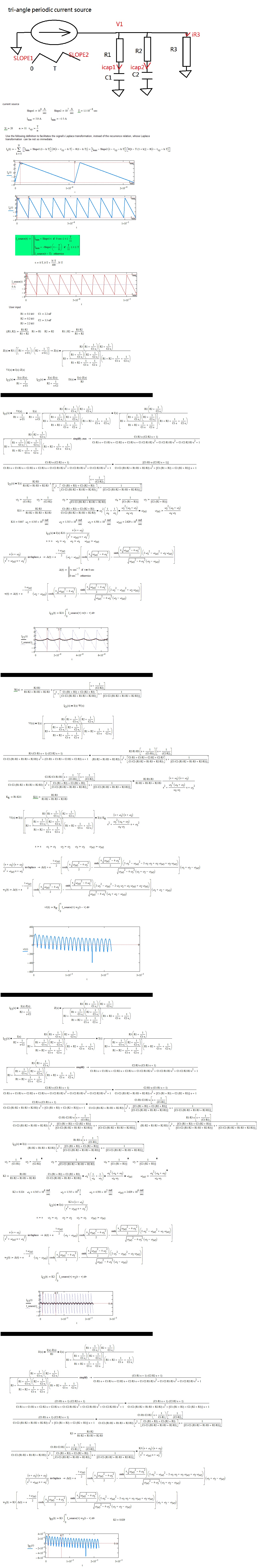
Now I find strange fact, that Ic1 has its concavity upwards and the other functions have the concavity downwards ....perhaps, it depends on the sign of the following differences:
Aug 02, 2016
12:12 PM
- Mark as New
- Bookmark
- Subscribe
- Mute
- Subscribe to RSS Feed
- Permalink
- Notify Moderator
Aug 02, 2016
12:12 PM
Hi F.M. thank you for your detailed advice. For my case, R1 and R2 are mOhm levels, while C1 and C2 are uF levels. R1 can range from 1Ohm to 0.1Ohm, will the strange fact you mentioned happen in this case?
Aug 02, 2016
12:30 PM
- Mark as New
- Bookmark
- Subscribe
- Mute
- Subscribe to RSS Feed
- Permalink
- Notify Moderator
Aug 02, 2016
12:30 PM
The phenomenon depends on the values of the angular frequencies and from the comparison among them.
I've added something about the Dirac pulse. It is shown the usefulness of the approximations to draw graphs with the Dirac pulse.
The file exceeds two MB so that it is cut.
Many greetings
FM

Aug 02, 2016
02:00 PM
- Mark as New
- Bookmark
- Subscribe
- Mute
- Subscribe to RSS Feed
- Permalink
- Notify Moderator
Aug 02, 2016
02:00 PM
Hi F.M, I have another question about I_source(t) and I(s) you are using. If I want to add more variables to the I_source(t), by keeping its current expression, I can change it to I_source(Slope1, Slope2, T, t). If so, should I directly use I_source(Slope1, Slope2, T, tao) at the inverse laplace transform? Thank you!
Aug 03, 2016
04:15 AM
- Mark as New
- Bookmark
- Subscribe
- Mute
- Subscribe to RSS Feed
- Permalink
- Notify Moderator
Aug 03, 2016
04:15 AM
If you are not sure about something, do the test.
Aug 06, 2016
12:16 AM
- Mark as New
- Bookmark
- Subscribe
- Mute
- Subscribe to RSS Feed
- Permalink
- Notify Moderator
Aug 06, 2016
12:16 AM
yhuang-3 wrote:
Hi F.M. thank you for your detailed advice. For my case, R1 and R2 are mOhm levels, while C1 and C2 are uF levels. R1 can range from 1Ohm to 0.1Ohm, will the strange fact you mentioned happen in this case?
Ah, for this range odesolve gives a better approximation. But need to take a very samll TOL.
Best regards.
Alvaro.
Aug 03, 2016
03:34 AM
- Mark as New
- Bookmark
- Subscribe
- Mute
- Subscribe to RSS Feed
- Permalink
- Notify Moderator
Aug 03, 2016
03:34 AM
Attached, numerical solution. As any numeric procedure, can fail for some combination of parameters (bad-conditioned problem).
Can't get the correct Derivative vector for call rkadopt, and others, but Odesolve works, at least, for few periods.
Best regards.
Alvaro.
Aug 03, 2016
04:53 AM
- Mark as New
- Bookmark
- Subscribe
- Mute
- Subscribe to RSS Feed
- Permalink
- Notify Moderator
Aug 03, 2016
04:53 AM
Hi Alvaro, I also wanted to take "your way" very interesting, to solve the problem, but then I opted for the network inspection method. I'm doing a comparison with my results, but I find some difficulties. Could you use the unit of measure and let us have the file, please? Thank you.
FM
Aug 03, 2016
05:05 PM
- Mark as New
- Bookmark
- Subscribe
- Mute
- Subscribe to RSS Feed
- Permalink
- Notify Moderator
Aug 03, 2016
05:05 PM
Hi F.M.
Can't use units with Odesolve because i is in Amperes, but I is for the integral of i along the time, then it is in A*sec. And can't mix units in the odesolve call with the vector (i1,i2,i3,I1,I2).
Best regards.
Alvaro.
Aug 06, 2016
01:55 PM
- Mark as New
- Bookmark
- Subscribe
- Mute
- Subscribe to RSS Feed
- Permalink
- Notify Moderator
Aug 06, 2016
01:55 PM
Hi Alvaro,
I would like to know why results are so different.
Thank you.
Bye
FM
Aug 06, 2016
02:03 PM
- Mark as New
- Bookmark
- Subscribe
- Mute
- Subscribe to RSS Feed
- Permalink
- Notify Moderator
Aug 06, 2016
02:03 PM
Hi F.M.
Check your TOL.
Alvaro.

Aug 07, 2016
05:11 AM
- Mark as New
- Bookmark
- Subscribe
- Mute
- Subscribe to RSS Feed
- Permalink
- Notify Moderator
Aug 07, 2016
05:11 AM
Thanks much for letting me know the mistake, it was a distraction.
Greetings
FM
Aug 04, 2016
06:34 PM
- Mark as New
- Bookmark
- Subscribe
- Mute
- Subscribe to RSS Feed
- Permalink
- Notify Moderator
Aug 04, 2016
06:34 PM
Hi F.M., I have another question about your solution. Would you tell me how did you express W(s) in trying to plot v(t)? I found that using laplace function, I cannot get W(S) from w(t). Thank you!
.JPG)
Aug 05, 2016
03:47 AM
- Mark as New
- Bookmark
- Subscribe
- Mute
- Subscribe to RSS Feed
- Permalink
- Notify Moderator
Aug 05, 2016
03:47 AM
Clarification: 1) In mathcad 15 isn't necessary to approximate the Dirac's delta.
2) for your problem see below and the attached worksheet
Bye
FM
Aug 05, 2016
01:41 PM
- Mark as New
- Bookmark
- Subscribe
- Mute
- Subscribe to RSS Feed
- Permalink
- Notify Moderator
Aug 05, 2016
01:41 PM
Hi F.M.,
I tried to use your initial worksheet and your latest worksheet little network.xmcd to sum I_C1,i_C2 and i_R3, and I found the sum of them do not equal to I_source(t), you can see the comparison here:
My questions are
(1) my first priority is to plot a relatively accurate V1(t), do you think the concavity issue or anything else will impact the plot of V1(t)?
(2) I tried to use your newly used bold L-1 symbol to calculate inverse Laplace. However, when I copied your code to my MathCAD 14, it shows like this. It is no longer bold. When I tried to use w(t):= L-1, Mathcad reports an error message that s is not defined. Do you know why it happens?
Thank you!
Aug 06, 2016
05:32 AM
- Mark as New
- Bookmark
- Subscribe
- Mute
- Subscribe to RSS Feed
- Permalink
- Notify Moderator
Aug 06, 2016
05:32 AM
Hi yhuang-3,
You should always use the last worksheet given by me.
[1] It is irrelevant
[2] In analysis, it is usual to indicate the inverse Laplace transform in this way. In mathcad environment you have to use the invlaplace operator.
It seems to me that you do not know the topic. Since it is very useful, you should deepen the study of the same.
Greetings
FM

Aug 08, 2016
08:27 AM
- Mark as New
- Bookmark
- Subscribe
- Mute
- Subscribe to RSS Feed
- Permalink
- Notify Moderator
Aug 08, 2016
08:27 AM
I would like to give you some advice, concerns the circuit presented by you is really an unacceptable draft, unpresentable. You should have draw a circuit like the one here below:
Greetings
FM

