
Turn on suggestions
Auto-suggest helps you quickly narrow down your search results by suggesting possible matches as you type.
Showing results for
Turn on suggestions
Auto-suggest helps you quickly narrow down your search results by suggesting possible matches as you type.
Showing results for
Community Tip - Did you get an answer that solved your problem? Please mark it as an Accepted Solution so others with the same problem can find the answer easily. X
- Community
- Creo+ and Creo Parametric
- 3D Part & Assembly Design
- 2D Cross sections in drawings
Options
- Subscribe to RSS Feed
- Mark Topic as New
- Mark Topic as Read
- Float this Topic for Current User
- Bookmark
- Subscribe
- Mute
- Printer Friendly Page
2D Cross sections in drawings
Aug 12, 2010
11:44 AM
- Mark as New
- Bookmark
- Subscribe
- Mute
- Subscribe to RSS Feed
- Permalink
- Notify Moderator
Aug 12, 2010
11:44 AM
2D Cross sections in drawings
I have a problem that neither I nor anybody at my company knows the answer to. I have a case, inside the case are electronic boards, electrical harnesses, and mechanical parts. I want to cut away part of the case and show specific elements of the interior. I know the you can do an X-section in the model and that will follow through into the drawing, however it is more difficult than that. The X-section that I draw is limited to a hard boundary line. I want to be able to create the cutout or cut-away but show some elements such as harnesses beyond the scope of the X-section while having everything else out of the picture.
I attached a picture to try to help me explain. The wires if you can see are cut off at the X-section boundary. I want to be able to specify that I want to see those wires beyond the boundary line and keep everything else the way it is. Is that possible?
by the way those callouts are not indicating what I'm talking about, they are just part of the drawing.
This thread is inactive and closed by the PTC Community Management Team. If you would like to provide a reply and re-open this thread, please notify the moderator and reference the thread. You may also use "Start a topic" button to ask a new question. Please be sure to include what version of the PTC product you are using so another community member knowledgeable about your version may be able to assist.
Labels:
- Labels:
-
General
6 REPLIES 6
Aug 12, 2010
01:45 PM
- Mark as New
- Bookmark
- Subscribe
- Mute
- Subscribe to RSS Feed
- Permalink
- Notify Moderator
Aug 12, 2010
01:45 PM
Christian,
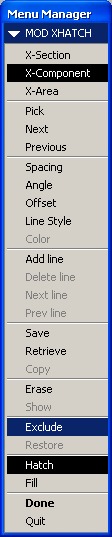
I think that what you may be looking for is found on the Menu Manager when editing properties on a cross-section in Drawing Mode. By selecting the x-hatching in the appropriate view, and then RMB properties you should see something like this. (I am in WF 4.0). Selecting Exclude from the lower portion of the Menu Manager should exclude that particular component from the cross section. I hope that this is what you are looking for.
-Greg
Aug 12, 2010
03:00 PM
- Mark as New
- Bookmark
- Subscribe
- Mute
- Subscribe to RSS Feed
- Permalink
- Notify Moderator
Aug 12, 2010
03:00 PM
Is there any way you could show me a picture or screen shot of what that does exactly. I'm in wildfire 5.0 so it's a little different. I was playing with that but didn't seem to do anything. Thanks
Aug 13, 2010
08:48 AM
- Mark as New
- Bookmark
- Subscribe
- Mute
- Subscribe to RSS Feed
- Permalink
- Notify Moderator
Aug 13, 2010
08:48 AM
Here is a PDF file of a rough model that I generated. It isn't perfect as the crosshatching needs broken around the tubing, but I think that this is close to what you are looking for. I also have WF5.0 installed on my machine. I have attached the rough sample drawing to this as well. The functionality is still there and the menu manager looks very similar to what I had posted yesterday. I did notice that I couldn't enter into this menu without having the layout tab active on the "ribbon" When any of the other tabs were active the properties selection on the RMB menu wasn't there. I also noticed that after making any changes to excluding or restoring components I had to switch over to the review tab on the "ribbon" and do an update sheets or update draft to be able to view the changes. A simple redraw didn't seem to do anything. Hope this helps.
-Greg
Aug 13, 2010
12:17 PM
- Mark as New
- Bookmark
- Subscribe
- Mute
- Subscribe to RSS Feed
- Permalink
- Notify Moderator
Aug 13, 2010
12:17 PM
I got into the menu you were talking about, but that seemed to only deal with the cross hatching and not the part or in this case with the file you sent me, the hose. The hose on the right was excluded from the cross section while the left hose was not. After I create the x-section in the 3D model, do I do anything with that section other than create it? It seems that what you're saying is this including and excluding of components is done solely in the drawing, and not the 3D model is that right?
Aug 17, 2010
11:46 AM
- Mark as New
- Bookmark
- Subscribe
- Mute
- Subscribe to RSS Feed
- Permalink
- Notify Moderator
Aug 17, 2010
11:46 AM
Yeah this command I am referring to only works in drawing mode. I understand that you are wanting to show this in assembly mode as a 3D model. Is that what you are interested in doing?
-Greg
Aug 17, 2010
02:16 PM
- Mark as New
- Bookmark
- Subscribe
- Mute
- Subscribe to RSS Feed
- Permalink
- Notify Moderator
Aug 17, 2010
02:16 PM
No, sorry to confuse you. I want this to display just like you showed me in drawing mode. My confusion is or was where to perform the command. From following (to the best of my knowledge) the screenshots and instructions you've given me the only thing I've been able to toggle is the cross hatching. I haven't been able to exclude or include any components or features (such as the hose in your example) from the drawing. Maybe if you could do a step by step of how to exclude that hose from the file you sent me. Thanks for your help!
