
Turn on suggestions
Auto-suggest helps you quickly narrow down your search results by suggesting possible matches as you type.
Showing results for
Turn on suggestions
Auto-suggest helps you quickly narrow down your search results by suggesting possible matches as you type.
Showing results for
- Community
- Creo+ and Creo Parametric
- 3D Part & Assembly Design
- Add visibly renderable silkscreen text and line ar...
Options
- Subscribe to RSS Feed
- Mark Topic as New
- Mark Topic as Read
- Float this Topic for Current User
- Bookmark
- Subscribe
- Mute
- Printer Friendly Page
Add visibly renderable silkscreen text and line art to surface
May 26, 2014
09:53 AM
- Mark as New
- Bookmark
- Subscribe
- Mute
- Subscribe to RSS Feed
- Permalink
- Notify Moderator
May 26, 2014
09:53 AM
Add visibly renderable silkscreen text and line art to surface
I have produced some sheet metal enclosures which will have silk screen printing added to identify connectors.
Is there a way I can add text and line art within Creo that will be rendered?
The only way I can think of doing is is having a seperate sketch with the text and line art, and then extrude it by an infinately small amount. Is there a "proper" way of doing it? In fact, scratch that, I just realised you cannot extrude text from a simple flat surface. 
So back to my initial question! 
Also, is there a way of inserting a variable in text that I can then pattern and have the variable increment in the pattern. Like "Input 1", "Input 2", etc, or do I have to manually do each one? <== I think I can forget about something like that for the moment!
This thread is inactive and closed by the PTC Community Management Team. If you would like to provide a reply and re-open this thread, please notify the moderator and reference the thread. You may also use "Start a topic" button to ask a new question. Please be sure to include what version of the PTC product you are using so another community member knowledgeable about your version may be able to assist.
Solved! Go to Solution.
Labels:
- Labels:
-
General
- Tags:
- silkscreen
1 ACCEPTED SOLUTION
Accepted Solutions
May 27, 2014
07:05 PM
- Mark as New
- Bookmark
- Subscribe
- Mute
- Subscribe to RSS Feed
- Permalink
- Notify Moderator
May 27, 2014
07:05 PM
My bad... you cannot extrude things in the sheetmetal module. This will work normally in regular part files.
Everything in a sheetmetal part must be the same thickness. Huge limitations in this respect.
So if you make a part file with the silkscreen only and assemble it with your sheetmetal part, you got it made. then you can detail the whole box using the sheetmetal part in most of your drawings, and then the assembly in the same drawing showing the silkscreen in its oven view.
Does that make sense?
20 REPLIES 20
May 26, 2014
10:22 AM
- Mark as New
- Bookmark
- Subscribe
- Mute
- Subscribe to RSS Feed
- Permalink
- Notify Moderator
May 26, 2014
10:22 AM
Hi,
We often have to do such renderings. To do our renderings we use Keyshot. For silkscreen printing I use PNG file that we create with Illustrator and then integrate it on my rendering.
I have tried to make extrude of texts, it's a lot of work only to get an approximate result !! And it makes your Creo model very "heavy" !!
May 26, 2014
02:25 PM
- Mark as New
- Bookmark
- Subscribe
- Mute
- Subscribe to RSS Feed
- Permalink
- Notify Moderator
May 26, 2014
02:25 PM
Merci Raphaël.
I didn't know about Keyshot. Downloading their demo version now to see if it could work.
Can you share some renders of some models you've created in Creo ?
Ahh, it would be an expensive solution by the looks of it... Difficult to justify for the ocassional render where I need text shown on top. Otherwise the built-in render (=no extra cost) is OK for me.
May 27, 2014
03:23 AM
- Mark as New
- Bookmark
- Subscribe
- Mute
- Subscribe to RSS Feed
- Permalink
- Notify Moderator
May 27, 2014
03:23 AM
Here's an example of what you could get with Keyshot. I've croped the image for confidentiality reason.
The only constraint to do this is to be able to generate a png of the silkscreening you want. For us it's easy because we also do silkscreening.
Concerning the cost, I think it's less expensive than the creo extension. And, regarding to the quality of the renderings, you can sell those to your customers. This is what we do, and now, some customers even use them on their websites !!
May 27, 2014
09:56 AM
- Mark as New
- Bookmark
- Subscribe
- Mute
- Subscribe to RSS Feed
- Permalink
- Notify Moderator
May 27, 2014
09:56 AM
Using textures (decal appearances) is a nice way to save really lighten the model. However, in order to have this show up in a drawing you need a shaded view to see it. There is also nothing to dimension to. If it is purely graphic for the model, indeed, this is a great option. Using an alpha channel graphic makes it even better since the background color can still be assigned through the appearance manager (for instance; using a black, gray, and tan as optional colors for the same part and using the same decal).
May 27, 2014
12:30 PM
- Mark as New
- Bookmark
- Subscribe
- Mute
- Subscribe to RSS Feed
- Permalink
- Notify Moderator
May 27, 2014
12:30 PM
Looks good, Raphael! thanks for sharing.
May 26, 2014
11:10 AM
- Mark as New
- Bookmark
- Subscribe
- Mute
- Subscribe to RSS Feed
- Permalink
- Notify Moderator
May 26, 2014
11:10 AM
I have to do this quite often for my sheetmetal efforts.
I do extrude the text from sections (sketches) by , say .004". However, I do prefer to do this as a separate component. In other words, I have a part level sheetmetal component and the next level assembly often has press-fit fasteners added... and optionally, I can add the silkscreen at that level, or the next level.
Silkscreen as a separate component in an assembly makes it easy to hide in drawings and even remove it through family tables or layers. I have not seen to much of an overhead for simple silkscreen requirements.
Since most industrial silkscreens use Helvetica as a font, I downloaded the open source SWISS 721 font which is nearly identical to Helvetica (licensed). If I do wish to specify SWISS 721, I can even make artwork ready geometry in this manner. What I am getting at is that you can add the right font to your session.
In my case, I detail the silkscreen to the full extent in my drawings. I detail offsets from features, height, font, font style, and all graphics including line thicknesses. -Anyone- can recreate the exact same artwork from my drawings in the case where suppliers are changes and no artmaster is managed or tracked by my client.
When you do extrude closed loop fonts, do not add tapers. Also, be sure to have the option of setting your accuracy to allow for the shallow extrude depth. Allow absolute accuracy in your config.pro and set your accuracy in the part file to maybe .0005 absolute. By default, these thin extrusions often fail.
May 26, 2014
01:53 PM
- Mark as New
- Bookmark
- Subscribe
- Mute
- Subscribe to RSS Feed
- Permalink
- Notify Moderator
May 26, 2014
01:53 PM
Antonius (or anyone) do you have any sample pics? I want to do more rendering when I have time, I'd like to see what results you guys are getting.
thanks!
May 26, 2014
02:28 PM
- Mark as New
- Bookmark
- Subscribe
- Mute
- Subscribe to RSS Feed
- Permalink
- Notify Moderator
May 26, 2014
02:28 PM
Same as what Matt said
I guess I'm doing something wrong as I cannot extrude my current text in a sketch. Is it a font limitation? Once you've added the SWISS 721 font, can you simply extrude the text geometry with the extrude function? Is it the fact it's a closed loop font that allows you to do it? Do you need to do anything on top to "create" the closed loop aspect? As you can tell, I'm still very new to Creo and often struggle with its crazy logic and user-unfriendliness.
I like the idea about having it as a separate part and then add it on top at the assembly stage. Neat trick!
May 27, 2014
10:07 AM
- Mark as New
- Bookmark
- Subscribe
- Mute
- Subscribe to RSS Feed
- Permalink
- Notify Moderator
May 27, 2014
10:07 AM
Yes, it has to be a closed loop font. The 3D_font is the default that works well. If the center of the text highlights as a closed boundary, it can be extruded as a solid.
Some fonts are not very good and will fail to recognize itself as a closed loop. You have to play with it, but it works fine. Remember not to have other geometry curves in the sketch that are not closed. You might be getting unrelated errors.
Creo out of the box doesn't do well with very thin extrusion on large panels (larger extent models) so you have to set the default accuracy and rather than using the default relative accuracy, you may need to use absolute accuracy. I always have allowing absolute accuracy enabled in config.pro. The fact that this requires a specific setting is beyond my comprehension.
May 27, 2014
12:33 PM
- Mark as New
- Bookmark
- Subscribe
- Mute
- Subscribe to RSS Feed
- Permalink
- Notify Moderator
May 27, 2014
12:33 PM
Looks good Antonius. And I agree about the accuracy.
May 27, 2014
01:27 PM
- Mark as New
- Bookmark
- Subscribe
- Mute
- Subscribe to RSS Feed
- Permalink
- Notify Moderator
May 27, 2014
01:27 PM
Accuracy settings allow the software to ignore deviations smaller than a certain amount. Particularly when tests for coincidence happen. It probably is most important in avoiding generating unnecessary tessellation, but also, for example, producing smooth intersections across surfaces with small offsets.
It would be nice to hear from the software developers what functions are driven by accuracy and the results of varied accuracy values and types are.
May 27, 2014
01:27 PM
- Mark as New
- Bookmark
- Subscribe
- Mute
- Subscribe to RSS Feed
- Permalink
- Notify Moderator
May 27, 2014
01:27 PM
Ahh I see why I couldn't extrude before: I was adding text on an existing surface but on its own. If I sketch a rectangle on the surface and then add the text inside, it works, but gives me the opposite of what I want: everything apart from the text is extruded. How do I "inverse" that?
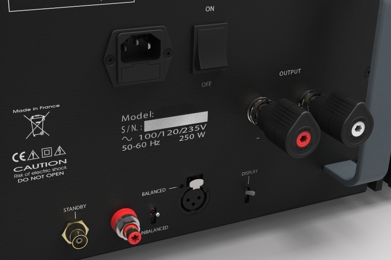
Thanks Raphaël, it does look good. Funnily enough, I'm also working on an audio power amplifier to which I want to add line printing just like you have I can easily add a PNG of the text on top, so that might be an easier option given how much I'm struggling to get what I want directly in Creo. I'll play with the demo version.
May 27, 2014
01:35 PM
- Mark as New
- Bookmark
- Subscribe
- Mute
- Subscribe to RSS Feed
- Permalink
- Notify Moderator
May 27, 2014
01:35 PM
Add one more rectangle and the extrude should inverse again... but you definitely shouldn't have to do that either.
Post your file here if you like and we can take a look at why it is not extruding. Just use the advanced editor.
May 27, 2014
02:53 PM
- Mark as New
- Bookmark
- Subscribe
- Mute
- Subscribe to RSS Feed
- Permalink
- Notify Moderator
May 27, 2014
02:53 PM
When I try to extrude it, I get a warning message: "The selected geometry can not be used by this tool. Please select new references."
Doing a simple rectangle seems to work 
Model attached.
May 27, 2014
07:05 PM
- Mark as New
- Bookmark
- Subscribe
- Mute
- Subscribe to RSS Feed
- Permalink
- Notify Moderator
May 27, 2014
07:05 PM
My bad... you cannot extrude things in the sheetmetal module. This will work normally in regular part files.
Everything in a sheetmetal part must be the same thickness. Huge limitations in this respect.
So if you make a part file with the silkscreen only and assemble it with your sheetmetal part, you got it made. then you can detail the whole box using the sheetmetal part in most of your drawings, and then the assembly in the same drawing showing the silkscreen in its oven view.
Does that make sense?
May 27, 2014
01:40 PM
- Mark as New
- Bookmark
- Subscribe
- Mute
- Subscribe to RSS Feed
- Permalink
- Notify Moderator
May 27, 2014
01:40 PM
Did you flip the direction arrow on which side is extruded?
May 27, 2014
03:15 PM
- Mark as New
- Bookmark
- Subscribe
- Mute
- Subscribe to RSS Feed
- Permalink
- Notify Moderator
May 27, 2014
03:15 PM
This is similar to the solution Antonious provided, but I create a sketch .001" offset from the sheetmetal surface. Then create a surface from the sketch. Now you can change the color of the surface for rendering, etc. and use layers to control visibility.
May 27, 2014
03:34 PM
- Mark as New
- Bookmark
- Subscribe
- Mute
- Subscribe to RSS Feed
- Permalink
- Notify Moderator
May 27, 2014
03:34 PM
Bill, the only problems I have with surfaces is that they do not do well for hidden line removal. they become obnoxious
May 27, 2014
03:57 PM
- Mark as New
- Bookmark
- Subscribe
- Mute
- Subscribe to RSS Feed
- Permalink
- Notify Moderator
May 27, 2014
03:57 PM
This is true enough. I suppose that it will depend on what other requirements you have. Sometimes we screen or laser etch on machined parts. We do not want the text / logos /part numbers to be solid as this will cause issues with machining (Creo Production Machining) and will cause issues with interference checks if you have the text on a mating surface.
May 27, 2014
05:42 PM
- Mark as New
- Bookmark
- Subscribe
- Mute
- Subscribe to RSS Feed
- Permalink
- Notify Moderator
May 27, 2014
05:42 PM
Good point
