
Turn on suggestions
Auto-suggest helps you quickly narrow down your search results by suggesting possible matches as you type.
Showing results for
Turn on suggestions
Auto-suggest helps you quickly narrow down your search results by suggesting possible matches as you type.
Showing results for
Community Tip - Did you know you can set a signature that will be added to all your posts? Set it here! X
- Community
- Creo+ and Creo Parametric
- 3D Part & Assembly Design
- Axis show small in hole when is makin with referen...
Options
- Subscribe to RSS Feed
- Mark Topic as New
- Mark Topic as Read
- Float this Topic for Current User
- Bookmark
- Subscribe
- Mute
- Printer Friendly Page
Axis show small in hole when is makin with reference axis
Aug 23, 2017
04:44 PM
- Mark as New
- Bookmark
- Subscribe
- Mute
- Subscribe to RSS Feed
- Permalink
- Notify Moderator
Aug 23, 2017
04:44 PM
Axis show small in hole when is makin with reference axis
Hello,
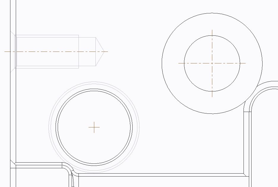
I am making perforations in one piece, these perforations are made taking as a reference a face and a refence axis normal to that face. Then I make other holes in the same piece but these I do without an axis, only with faces as references. At the time of the drawing the perforations that were made taking as a reference a face and an axis show me their short (small) axes, in contrast the other perforations that were made with references only of faces show me their axes well (the axes of Are extended to the limit of the circumference). See attached images. A solution so that the reference axes of both holes are always shown well (the axes extended to the circumference limit) would be great. The parts planes that I realize have too many perforations so it is tedious to increase the size of the drilling axes. Who knows how to show all the axes of refence well ?.
abustamante
Solved! Go to Solution.
Labels:
- Labels:
-
General
1 ACCEPTED SOLUTION
Accepted Solutions
Aug 23, 2017
09:08 PM
- Mark as New
- Bookmark
- Subscribe
- Mute
- Subscribe to RSS Feed
- Permalink
- Notify Moderator
Aug 23, 2017
09:08 PM
Yes, I see the same thing in Creo 3.0, M120. Holes made using the face+axis as references show their axes as a small cross. For other hole placement schemes, it seems the hole axis cross-hairs extend beyond the edge of the hole. Sure seems like a bug.
If you must use the axis+face method, then I don't have a solution for you; however, I recommend using the sketch pattern as means of arranging the placement of a series of holes on the same planar surface:
1) start the sketch tool and use the face that will be drilled as the sketch placement plane
2) choose your references and start sketching
3) add as many points as you have holes that will be drilled in this face. You can use (construction) geometry to establish the point locations. Important Note: you must use "geometry points" (not "construction points"!) to mark the drill point locations.
4) End the sketch and then select it in the model tree and start the hole tool - you will see it will start the hole at the 1st sketched point and it will be normal to the sketch surface. Customize your hole, then finish placing the hole.
5) after the hole is made, select its feature in the model tree, and use the "Pattern" tool -> change type to Point -> and then select the sketch you drew at step 3/4. Sometimes, when using the sketch patterns, you might have to use the pattern options->Use alternate origin - but for most holes that are drilled normal to the face, it usually just works.
6) in your drawing, you show the dimensions of the sketch feature in order to present the hole pattern dimensioning scheme.
I find it much easier to work with sketches than with pattern tables b/c you have access to the construction geometry and also the entire geometric constraint functionality.
3 REPLIES 3
Aug 23, 2017
09:08 PM
- Mark as New
- Bookmark
- Subscribe
- Mute
- Subscribe to RSS Feed
- Permalink
- Notify Moderator
Aug 23, 2017
09:08 PM
Yes, I see the same thing in Creo 3.0, M120. Holes made using the face+axis as references show their axes as a small cross. For other hole placement schemes, it seems the hole axis cross-hairs extend beyond the edge of the hole. Sure seems like a bug.
If you must use the axis+face method, then I don't have a solution for you; however, I recommend using the sketch pattern as means of arranging the placement of a series of holes on the same planar surface:
1) start the sketch tool and use the face that will be drilled as the sketch placement plane
2) choose your references and start sketching
3) add as many points as you have holes that will be drilled in this face. You can use (construction) geometry to establish the point locations. Important Note: you must use "geometry points" (not "construction points"!) to mark the drill point locations.
4) End the sketch and then select it in the model tree and start the hole tool - you will see it will start the hole at the 1st sketched point and it will be normal to the sketch surface. Customize your hole, then finish placing the hole.
5) after the hole is made, select its feature in the model tree, and use the "Pattern" tool -> change type to Point -> and then select the sketch you drew at step 3/4. Sometimes, when using the sketch patterns, you might have to use the pattern options->Use alternate origin - but for most holes that are drilled normal to the face, it usually just works.
6) in your drawing, you show the dimensions of the sketch feature in order to present the hole pattern dimensioning scheme.
I find it much easier to work with sketches than with pattern tables b/c you have access to the construction geometry and also the entire geometric constraint functionality.
Aug 23, 2017
10:20 PM
- Mark as New
- Bookmark
- Subscribe
- Mute
- Subscribe to RSS Feed
- Permalink
- Notify Moderator
Aug 23, 2017
10:20 PM
The axes that exist before the holes exist don't have a size reference so when Creo goes down the list of features it sees the axis has no size reference.
The axes that are created as part of the hole are made after the surface of the hole so they do have a size reference.
Creo developers probably didn't want to add a second axis on top of the first one when using an axis as a placement reference.
Using a reference other than an axis should cause Creo to create the secondary axis.
Aug 24, 2017
10:07 AM
- Mark as New
- Bookmark
- Subscribe
- Mute
- Subscribe to RSS Feed
- Permalink
- Notify Moderator
Aug 24, 2017
10:07 AM
Thanks for the valuable contribution of all.
This solution seems feasible, since I have tried in many ways to show the extended axes in the pre-created reference perforations. The only tedious thing is that I will have to use the option to select alternative origin, since it has happened to me that perforations made with dot patterns come out in different locations, they move, so I will have to use the option to select origin point in the pattern To control it properly.
And thanks also for the clarification of understanding what happens when you use a previously made axis of refence, everything is understood.
Thank you all for your valuable contribution.
abustamante
