
Turn on suggestions
Auto-suggest helps you quickly narrow down your search results by suggesting possible matches as you type.
Showing results for
Turn on suggestions
Auto-suggest helps you quickly narrow down your search results by suggesting possible matches as you type.
Showing results for
Community Tip - If community subscription notifications are filling up your inbox you can set up a daily digest and get all your notifications in a single email. X
- Community
- Creo+ and Creo Parametric
- 3D Part & Assembly Design
- Re: Bend to end of surface after flanges
Options
- Subscribe to RSS Feed
- Mark Topic as New
- Mark Topic as Read
- Float this Topic for Current User
- Bookmark
- Subscribe
- Mute
- Printer Friendly Page
Bend to end of surface after flanges
Dec 05, 2017
07:08 PM
- Mark as New
- Bookmark
- Subscribe
- Mute
- Subscribe to RSS Feed
- Permalink
- Notify Moderator
Dec 05, 2017
07:08 PM
Bend to end of surface after flanges
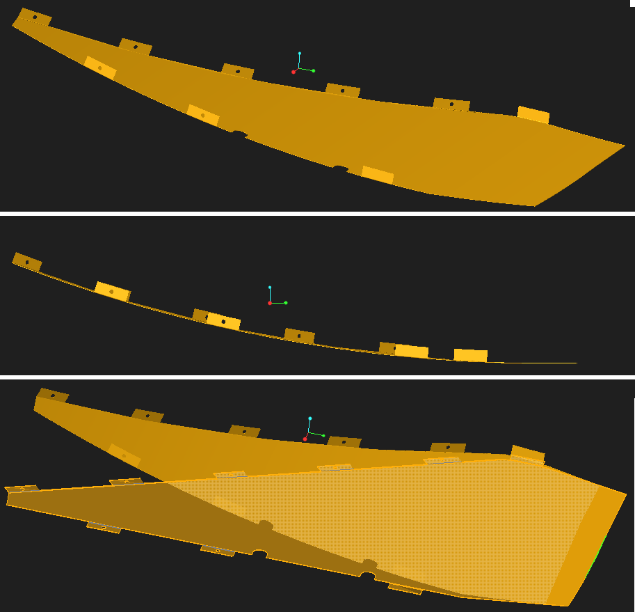
Using Creo 4.0 and I'm trying to get a part that can be in both a rolled state with flanges and a flat state. I have tried all sorts of combinations of creating the roll first then the flanges, making a flange all the way around, extruding out the tabs, and then trying to roll it. When I can get the final part the way I want and select Flat Pattern, it will act like it's going to work, but then fail to regenerate (bottom image), I can't get it to flatten out using unbend or bend back (what is the difference??) Nothing has worked so far and I am not very experienced user. Any advice will be much appreciated! Thank you!
Solved! Go to Solution.
1 ACCEPTED SOLUTION
Accepted Solutions
Dec 05, 2017
09:37 PM
- Mark as New
- Bookmark
- Subscribe
- Mute
- Subscribe to RSS Feed
- Permalink
- Notify Moderator
Dec 05, 2017
09:37 PM
Sheetmetal does not allow flattening of intersecting bends. In general, if the part cannot be formed using a sheet metal brake then it cannot be formed/flattened in the sheetmetal module.
You can see the effect if you take a piece of paper, cut a shape that is similar to what you expect the pattern to be and then see what happens when you try to fold the tabs and then make the large curve. To do otherwise requires stretching the shape of the part; Creo can't calculate that.
The same is true of SolidWorks, if their help forums are correct.
I'm impressed Creo got as far as it did.
3 REPLIES 3
Dec 05, 2017
09:37 PM
- Mark as New
- Bookmark
- Subscribe
- Mute
- Subscribe to RSS Feed
- Permalink
- Notify Moderator
Dec 05, 2017
09:37 PM
Sheetmetal does not allow flattening of intersecting bends. In general, if the part cannot be formed using a sheet metal brake then it cannot be formed/flattened in the sheetmetal module.
You can see the effect if you take a piece of paper, cut a shape that is similar to what you expect the pattern to be and then see what happens when you try to fold the tabs and then make the large curve. To do otherwise requires stretching the shape of the part; Creo can't calculate that.
The same is true of SolidWorks, if their help forums are correct.
I'm impressed Creo got as far as it did.
Dec 07, 2017
02:18 AM
- Mark as New
- Bookmark
- Subscribe
- Mute
- Subscribe to RSS Feed
- Permalink
- Notify Moderator
Dec 07, 2017
02:18 AM
@dschenken wrote:
Sheetmetal does not allow flattening of intersecting bends. In general, if the part cannot be formed using a sheet metal brake then it cannot be formed/flattened in the sheetmetal module.
That's not entirely accurate. We unfold louvres which are curved in two directions in the sheetmetal environment with Creo.
Manufacturing whise (IRL) we first bend the louvre, then we use a three-rolls-bending machine to add the curvature to the louvre.


Dec 07, 2017
02:49 AM
- Mark as New
- Bookmark
- Subscribe
- Mute
- Subscribe to RSS Feed
- Permalink
- Notify Moderator
Dec 07, 2017
02:49 AM
From the views given the flat pattern should not result in the part shown. The vertical parts at the ends of the flange appear parallel to each other when formed, which is not the result of the shown flat pattern being formed, which looks to have straight-cut ends.
Perhaps Creo now approximates two-way results; the result doesn't look correct.
