
Turn on suggestions
Auto-suggest helps you quickly narrow down your search results by suggesting possible matches as you type.
Showing results for
Turn on suggestions
Auto-suggest helps you quickly narrow down your search results by suggesting possible matches as you type.
Showing results for
Community Tip - Did you get an answer that solved your problem? Please mark it as an Accepted Solution so others with the same problem can find the answer easily. X
- Community
- Creo+ and Creo Parametric
- 3D Part & Assembly Design
- Centrifugal Loading
Options
- Subscribe to RSS Feed
- Mark Topic as New
- Mark Topic as Read
- Float this Topic for Current User
- Bookmark
- Subscribe
- Mute
- Printer Friendly Page
Centrifugal Loading
Jun 04, 2013
05:47 AM
- Mark as New
- Bookmark
- Subscribe
- Mute
- Subscribe to RSS Feed
- Permalink
- Notify Moderator
Jun 04, 2013
05:47 AM
Centrifugal Loading
Hi, I am running Creo Parametric 1.0 and I am having problems applying constraints for an object with centrifugal loads.
To start with I have a simple solid steel disc 400mm dia by 50mm thick. I can specify the axis and speed of rotation but how do I apply the constraints?
The things I dont want to move are the disc axis radially and the centre plane of the disc axially - any ideas?
This thread is inactive and closed by the PTC Community Management Team. If you would like to provide a reply and re-open this thread, please notify the moderator and reference the thread. You may also use "Start a topic" button to ask a new question. Please be sure to include what version of the PTC product you are using so another community member knowledgeable about your version may be able to assist.
Solved! Go to Solution.
Labels:
- Labels:
-
General
1 ACCEPTED SOLUTION
Accepted Solutions
Jun 04, 2013
05:51 AM
- Mark as New
- Bookmark
- Subscribe
- Mute
- Subscribe to RSS Feed
- Permalink
- Notify Moderator
Jun 04, 2013
05:51 AM
Hi Bob,
Cyclic symmetry is really useful for providing a 'centre' constraint as well as speeding up the run. Then you can apply the axial constraint on a bore surface, or perhaps a surface region on an end face.
You can't constrain a plane as such - it has to be solid geometry.
If your part isn't amenable to cyclic symmetry, you'll have to start playing with weighted links and springs to avoid over-constraint - useful, but more long-winded to set up than a cyclic symmetry.
4 REPLIES 4
Jun 04, 2013
05:51 AM
- Mark as New
- Bookmark
- Subscribe
- Mute
- Subscribe to RSS Feed
- Permalink
- Notify Moderator
Jun 04, 2013
05:51 AM
Hi Bob,
Cyclic symmetry is really useful for providing a 'centre' constraint as well as speeding up the run. Then you can apply the axial constraint on a bore surface, or perhaps a surface region on an end face.
You can't constrain a plane as such - it has to be solid geometry.
If your part isn't amenable to cyclic symmetry, you'll have to start playing with weighted links and springs to avoid over-constraint - useful, but more long-winded to set up than a cyclic symmetry.
Jun 18, 2013
03:21 AM
- Mark as New
- Bookmark
- Subscribe
- Mute
- Subscribe to RSS Feed
- Permalink
- Notify Moderator
Jun 18, 2013
03:21 AM
Jonathan,
Sorry to be so late getting back to you, but many thanks for the advice.
I am back at my desk now and will be giving it a go very shortly.
Regards,
Bob
Jun 04, 2013
08:25 AM
- Mark as New
- Bookmark
- Subscribe
- Mute
- Subscribe to RSS Feed
- Permalink
- Notify Moderator
Jun 04, 2013
08:25 AM
Bob,
Like Jonathan mentions, the cyclic symmetry is a smart way to go for a number of reasons, so use it if you can. I think there are a couple of ways that you can constrain the disk and you will want to test these out to make sure the disk is behaving the way you expect. You can always use hand calcs on a simple disk like this to verify the FEA. Below is one way that I think will work.
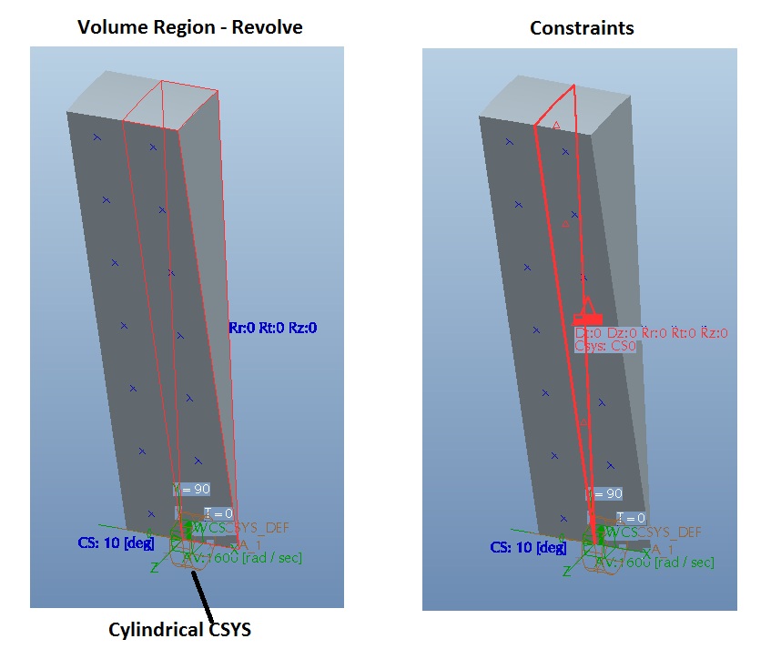
1) Before going into Mechanica create a cut that leaves a small pie shape portion of your disk, maybe 10 degrees or even smaller.
2) Once in Mechanica create a volume region that axially splits your part into two equal volumes and this will by default create the center plane that you are looking to constrain.
3) Setup a cylindrical CSYS in your model. It is probably easier to work with rotating parts/assemblies using a cylindrical CSYS versus Cartesian.
5) Apply your cyclic symmetry constraint.
6) Apply your center plane constraint, constraining axial movement of this centerplane. I used a cylindrical CSYS and left only Dr as free
6) Apply the centrifugal load
7) Run the analysis
Another way is similar to what Jonathan mentioned and involves constraining the end faces plus an additional constraint at the midpoint of the part axis. As you get away from simple disk cases, you will need to use other options in setting up your constraints.
Hope this helps get you going,
Jon
Jun 18, 2013
03:24 AM
- Mark as New
- Bookmark
- Subscribe
- Mute
- Subscribe to RSS Feed
- Permalink
- Notify Moderator
Jun 18, 2013
03:24 AM
Jonathan,
Sorry to be so late getting back to you, but many thanks for your advice.
Back at my desk now and I am just about to start giving it a go.
Regards,
Bob
