
Turn on suggestions
Auto-suggest helps you quickly narrow down your search results by suggesting possible matches as you type.
Showing results for
Turn on suggestions
Auto-suggest helps you quickly narrow down your search results by suggesting possible matches as you type.
Showing results for
Community Tip - Have a PTC product question you need answered fast? Chances are someone has asked it before. Learn about the community search. X
- Community
- Creo+ and Creo Parametric
- 3D Part & Assembly Design
- Creating angular and diametral quotations
Options
- Subscribe to RSS Feed
- Mark Topic as New
- Mark Topic as Read
- Float this Topic for Current User
- Bookmark
- Subscribe
- Mute
- Printer Friendly Page
Creating angular and diametral quotations
Mar 23, 2014
09:25 AM
- Mark as New
- Bookmark
- Subscribe
- Mute
- Subscribe to RSS Feed
- Permalink
- Notify Moderator
Mar 23, 2014
09:25 AM
Creating angular and diametral quotations
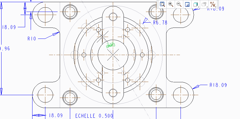
Hello, how do you create angular and diametral quotations with creo parametric ? Here is the project I'm working on :
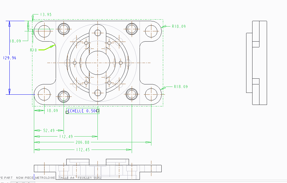
When I quotate with the tool 'quotation', it only quotates radius of the circles, and not diameter. I also need to quotate the angle between the vertical plan going through the center of the part and one of the circle located on an given radius (as you can notice, there are 6 circles exactly the same, located on the same radius but with an incremental angle of 60 degrees). How can I do that withouth creating another line going from the center of the part to the center of
one of these circles, like I have done on the below example. I know it's possible because when I select 'add annotations to this view', this angular cotation is added without any additionnal line. I thought it was possible to hide this line but it's not.
Thanks in advance for your help !
This thread is inactive and closed by the PTC Community Management Team. If you would like to provide a reply and re-open this thread, please notify the moderator and reference the thread. You may also use "Start a topic" button to ask a new question. Please be sure to include what version of the PTC product you are using so another community member knowledgeable about your version may be able to assist.
Labels:
- Labels:
-
General
1 REPLY 1
Mar 23, 2014
02:24 PM
- Mark as New
- Bookmark
- Subscribe
- Mute
- Subscribe to RSS Feed
- Permalink
- Notify Moderator
Mar 23, 2014
02:24 PM
Welcome ot the forum.
I am not understanding your questi0jn very well, but I will try to help with the basics of what is needed.
In the drawing configuration options (not config.pro), look for radial_pattern_axis_circle and set this to YES.
This will create a circular axis symbols to show concentric patterns.
Next, in the model, you can create the pattern using a Diameter dimension for the bolt circle dimension. You can show this dimension in your drawing using the Show Annotation dialog. Unfortunately, you cannot dimension the circle of the bolt circle centerline! Once the dimension is shown from the annotation dialog, you can select it and through a right click, you can change the orientation of the arrows. You can have outside-single, outside-dial, or inside-dual arrows. In some instances, the outside dual will have an extension through the center. I am not sure if this is dependent on the selected drafting standard.
You can dimension an angle to the individual axes of the bolt pattern axes. once you set the option as noted above, you can use the axes for all angular dimension annotation. You can change the length of the angle dimension leaders by highlighting the dimension and dragging the ends of the leader. You can make them short, but you cannot hide them completely.
So there are two things I don't like about this method of annotation: 1 - you cannot dimension the axes diameter circle, and 2 - the fact that the radial pattern axes is not a default is a real shame.
Please let us know if there are more questions you are wanting answered.
