
Turn on suggestions
Auto-suggest helps you quickly narrow down your search results by suggesting possible matches as you type.
Showing results for
Turn on suggestions
Auto-suggest helps you quickly narrow down your search results by suggesting possible matches as you type.
Showing results for
Community Tip - Learn all about the Community Ranking System, a fun gamification element of the PTC Community. X
- Community
- Creo+ and Creo Parametric
- 3D Part & Assembly Design
- RE: Dimensioning Compound Angles and Curves
Options
- Subscribe to RSS Feed
- Mark Topic as New
- Mark Topic as Read
- Float this Topic for Current User
- Bookmark
- Subscribe
- Mute
- Printer Friendly Page
Dimensioning Compound Angles and Curves
Jan 17, 2013
07:00 PM
- Mark as New
- Bookmark
- Subscribe
- Mute
- Subscribe to RSS Feed
- Permalink
- Notify Moderator
Jan 17, 2013
07:00 PM
Dimensioning Compound Angles and Curves
I've been tasked to create a drawing for a part that has multiple Compound Angles & Curves. In the past for similar parts, X Y Z data was sufficient. But this part has holes all around the perimeter AND they want the hole locations dimensioned. Other than using the 3D Model as the drawing, I have no clue how to create the drawing?
Any suggestions?
Note: I am unable to send a screenshot as this is customer proprietary. Also, all I have access to is an IGES file.
Thanks.
-Art
.
.
.
.
This message (including any attachments) contains
confidential and/or proprietary information intended
only for the addressee. Any unauthorized disclosure,
copying, distribution or reliance on the contents of this
information is strictly prohibited and may constitute a violation
of law. If you are not the intended recipient, please notify the
sender immediately by responding to this e-mail, and delete the
message from your system. If you have any questions about this
e-mail please notify the sender immediately.
This thread is inactive and closed by the PTC Community Management Team. If you would like to provide a reply and re-open this thread, please notify the moderator and reference the thread. You may also use "Start a topic" button to ask a new question. Please be sure to include what version of the PTC product you are using so another community member knowledgeable about your version may be able to assist.
Labels:
- Labels:
-
General
3 REPLIES 3
Jan 18, 2013
01:08 PM
- Mark as New
- Bookmark
- Subscribe
- Mute
- Subscribe to RSS Feed
- Permalink
- Notify Moderator
Jan 18, 2013
01:08 PM
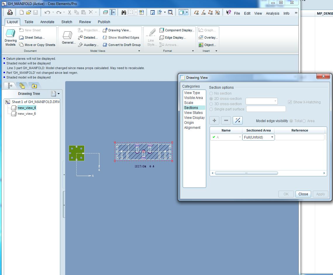
2D offset cross-section in a Full(Unfolded) section option? In one view you will have the path of the cross section defined, and in a independent view you lay out cross-section flat. See attached.
Tim P. Cooper
Jan 18, 2013
02:46 PM
- Mark as New
- Bookmark
- Subscribe
- Mute
- Subscribe to RSS Feed
- Permalink
- Notify Moderator
Jan 18, 2013
02:46 PM
Depending on the needs of the part hole location requirements, you would
need to dimension the x,y,z location of the 'pierce point' of the hole
on the face, and then provide dimensions as needed to find this point,
and make the assumption that the hole axis is normal to the piercing
face.
Thinking of the part the way a Machinist on a Bridgeport Mill would see
it, you may need several aux views, one for each facet face that has a
hole in it showing the location of this hole as seen straight on to some
other features, edges... On really complicated fixtures with compound
features, I would show the location of a gage ball on a stick (common
carr-lane item) to generic hole in the part, and dimension all features
to this.
Too bad you can't show us an example of what the part looks like. Might
be fun to dimension. (BTW, I have a strange idea of 'fun')
Christopher F. Gosnell
FPD Company
124 Hidden Valley Road
McMurray, PA 15317
Jan 20, 2013
07:49 AM
- Mark as New
- Bookmark
- Subscribe
- Mute
- Subscribe to RSS Feed
- Permalink
- Notify Moderator
Jan 20, 2013
07:49 AM
No matter how one dresses it up...it's all stilljust Drafting! 🐵 How many remember their Descriptive Geometry, hmmmm?
Score one for the Old Dogs.
