
Turn on suggestions
Auto-suggest helps you quickly narrow down your search results by suggesting possible matches as you type.
Showing results for
Turn on suggestions
Auto-suggest helps you quickly narrow down your search results by suggesting possible matches as you type.
Showing results for
Community Tip - Learn all about PTC Community Badges. Engage with PTC and see how many you can earn! X
- Community
- Creo+ and Creo Parametric
- 3D Part & Assembly Design
- Drill sequences in 4 axis manufacturing
Options
- Subscribe to RSS Feed
- Mark Topic as New
- Mark Topic as Read
- Float this Topic for Current User
- Bookmark
- Subscribe
- Mute
- Printer Friendly Page
Drill sequences in 4 axis manufacturing
May 14, 2012
08:13 AM
- Mark as New
- Bookmark
- Subscribe
- Mute
- Subscribe to RSS Feed
- Permalink
- Notify Moderator
May 14, 2012
08:13 AM
Drill sequences in 4 axis manufacturing
Hi
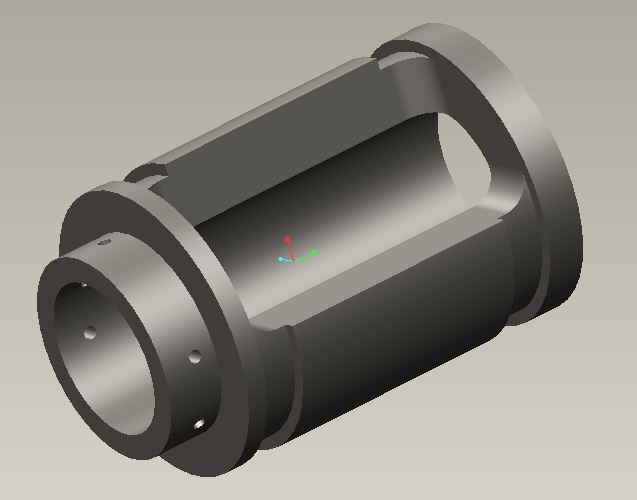
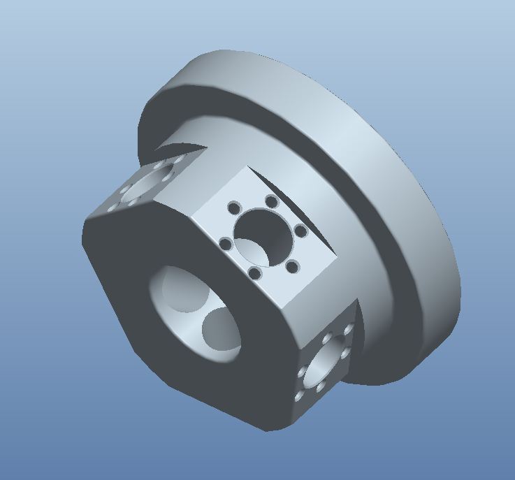
I run a 4 axis mill wich the fourth axis is an A axis- revolving around the x axis. I want to use the drill and roughing sequences but do not succeed. In some of te sequences i can choose either 3,4 or 5 axis. but not the ones i've mentioned above. Is there anyone who have experience with these? There must be a way to make holes in a part using 4 axis. Look at attached picture for an example to solve
Odd Eirik
Norway
This thread is inactive and closed by the PTC Community Management Team. If you would like to provide a reply and re-open this thread, please notify the moderator and reference the thread. You may also use "Start a topic" button to ask a new question. Please be sure to include what version of the PTC product you are using so another community member knowledgeable about your version may be able to assist.
Solved! Go to Solution.
Labels:
- Labels:
-
General
1 ACCEPTED SOLUTION
Accepted Solutions
Jul 18, 2012
04:53 PM
- Mark as New
- Bookmark
- Subscribe
- Mute
- Subscribe to RSS Feed
- Permalink
- Notify Moderator
Jul 18, 2012
04:53 PM
Matt,
I got it working!!! The reason why it wasn't working properly was that, the tool compensation was set to tool edge instead tool center. Thanks a lot man. Its all about the details.......
Regards,
Paul
31 REPLIES 31
May 18, 2012
11:44 AM
- Mark as New
- Bookmark
- Subscribe
- Mute
- Subscribe to RSS Feed
- Permalink
- Notify Moderator
May 18, 2012
11:44 AM
You have to have the workcell as 5 axis and use process manager. That will give you the option to create a drill 5 axis drill sequence, there is no 4 axis drill sequence.
Jun 27, 2012
12:41 PM
- Mark as New
- Bookmark
- Subscribe
- Mute
- Subscribe to RSS Feed
- Permalink
- Notify Moderator
Jun 27, 2012
12:41 PM
Hello,
From the looks of your picture all you need is indexing to bore the holes in. All you have to do is create a cys at each hole then when you create your nc sequence pick the correct cys for the hole you want to machine. This will point the tool vector in a different angle and you will get a A axis output in your code. When I set a 4axis or indexing job up I usually work from the center of my part. I create a main cys then just rotate multiple cys at what ever angles I will be machining at. Then when you start creating your nc sequences you already are set up just pick the cys you want and retract distance for your tool. In your operation set up you can create a clear distance for rotary clearance. You will also need to make sure your post is set up for this. I f you need anymore help just let me know I will be glad to help you get going on your project.
Jul 11, 2012
05:10 PM
- Mark as New
- Bookmark
- Subscribe
- Mute
- Subscribe to RSS Feed
- Permalink
- Notify Moderator
Jul 11, 2012
05:10 PM
Hello Matt,
Just a question. Do you have experience with milling on the 4th axis? Drilling holes is no problem for me, i use a simular option that you mentioned. I spent so many hours on cutting a segment out of a revolve. The 4-th axis is also an A axis revolving arround the X-axis. The only thing that worked a bit was a trajectory milling, but it is not done perfectly. Tommorow i will start a new project where this also needs an 60 degree of pie material out of a revolve. I will program this in Creo 2.0 Maybe Ptc simplified it.
Kind regards,
Paul
Jul 11, 2012
05:17 PM
- Mark as New
- Bookmark
- Subscribe
- Mute
- Subscribe to RSS Feed
- Permalink
- Notify Moderator
Jul 12, 2012
07:55 AM
- Mark as New
- Bookmark
- Subscribe
- Mute
- Subscribe to RSS Feed
- Permalink
- Notify Moderator
Jul 12, 2012
07:55 AM
Hey Matt,
See the picture for the project i am currently working on. What is difficult form me, is mill the material away on the outside of the material. The only way a think i can make this work is programming this to use a trajectory. What i like is a volume milling sequence. Any sugestions?
Looking forward to your reaction,
Paul
Jul 12, 2012
11:08 AM
- Mark as New
- Bookmark
- Subscribe
- Mute
- Subscribe to RSS Feed
- Permalink
- Notify Moderator
Jul 12, 2012
11:08 AM
Paul,
Unfortunately pro does not allow full 4 axis using volume rough hopefully in the future they will look at this. But for now have you tried just a index to the center of the pie shape using volume rough then let it use full 3 axis to rough the pie shape out then go back with a trajectory and finish the walls?
Jul 12, 2012
11:13 AM
- Mark as New
- Bookmark
- Subscribe
- Mute
- Subscribe to RSS Feed
- Permalink
- Notify Moderator
Jul 12, 2012
11:13 AM
While you can't volume mill 4 axis you can surface mill. Surface milling will follow the contour and can be used to somewhat rought out the part.
Jul 12, 2012
11:17 AM
- Mark as New
- Bookmark
- Subscribe
- Mute
- Subscribe to RSS Feed
- Permalink
- Notify Moderator
Jul 12, 2012
11:17 AM
Yes that is true but it seems like you would have to do multiple surface milling steps with different stock allowances to get there.
Jul 12, 2012
11:29 AM
- Mark as New
- Bookmark
- Subscribe
- Mute
- Subscribe to RSS Feed
- Permalink
- Notify Moderator
Jul 12, 2012
11:29 AM
I used a 3-axis volume mill to rough it out. At the moment i am wrestling with a profile mill sequence for finishing the surface. I created a surfacemill -sweep to define the surface, but the tool is limmited on the depth where it mill. I use an entry a an axis it goes to the wright depth put teh it steps back. 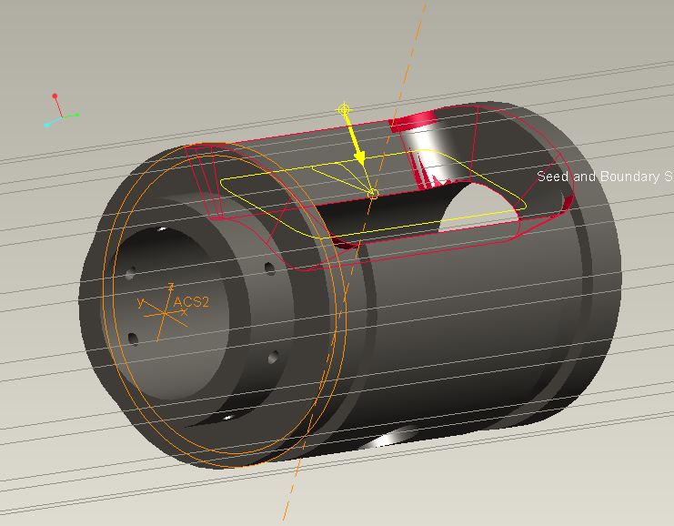
Anyone an idea?
Jul 12, 2012
11:44 AM
- Mark as New
- Bookmark
- Subscribe
- Mute
- Subscribe to RSS Feed
- Permalink
- Notify Moderator
Jul 12, 2012
11:44 AM
You can do 4+ axis profile milling if you add the config option 5_axis_side_mill yes.
Jul 12, 2012
12:11 PM
- Mark as New
- Bookmark
- Subscribe
- Mute
- Subscribe to RSS Feed
- Permalink
- Notify Moderator
Jul 12, 2012
12:11 PM
Have you tried a 4 axis trajectory?
Jul 12, 2012
12:29 PM
- Mark as New
- Bookmark
- Subscribe
- Mute
- Subscribe to RSS Feed
- Permalink
- Notify Moderator
Jul 12, 2012
12:29 PM
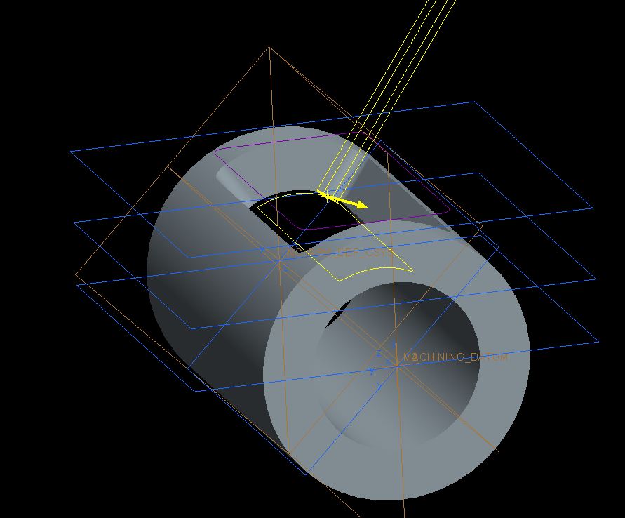
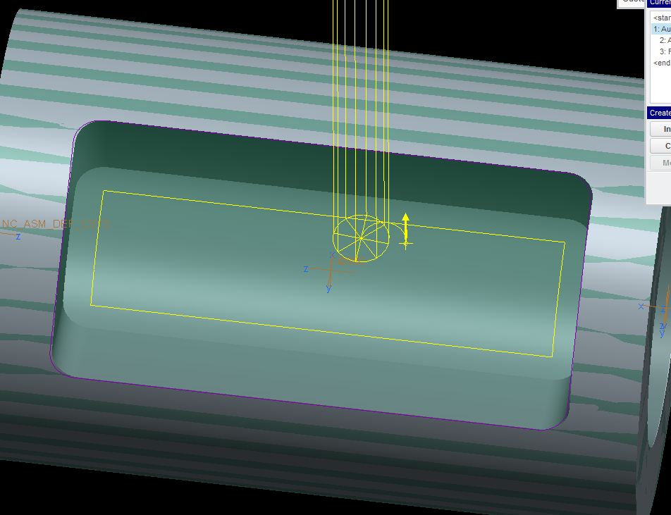
Paul try a 4 axis trajectory you can create your start and end height. I created this simple pie shape cut in a round part similar to what you are doing. The trajectory gives you more control over the tool path.
Jul 12, 2012
04:27 PM
- Mark as New
- Bookmark
- Subscribe
- Mute
- Subscribe to RSS Feed
- Permalink
- Notify Moderator
Jul 12, 2012
04:27 PM
Hello Matt,
I dont know what i do wrong but, it will not work for me with an start and end height. What do you use for the start height? I asume its not a plane?
Regards,
Paul
Jul 12, 2012
04:44 PM
- Mark as New
- Bookmark
- Subscribe
- Mute
- Subscribe to RSS Feed
- Permalink
- Notify Moderator
Jul 12, 2012
04:44 PM
Just create some planes similar to what I have in the picture I posted then you have to check start height in the define cut window also the end height should be by default already checked. Then insert the cut and if you read the bottom of the screen pro will be prompting you to pick things. I am not very good at explaining things if this does not help I will take some screen shots of how to do it step by step and post them. Also for start and end height you will have a option to pick a plane. You should also get a prompt for axis control to. I will try to put something together I do not know if I will have time today.
Jul 12, 2012
05:12 PM
- Mark as New
- Bookmark
- Subscribe
- Mute
- Subscribe to RSS Feed
- Permalink
- Notify Moderator
Jul 12, 2012
05:12 PM
Hello Matt,
Thank you for all the help so far, It's been appreciated very much. Can you use axis shift as depth control too? I often use this option for deburring.
Regards,
Paul
Jul 13, 2012
07:12 AM
- Mark as New
- Bookmark
- Subscribe
- Mute
- Subscribe to RSS Feed
- Permalink
- Notify Moderator
Jul 13, 2012
07:12 AM
Yes you can but just be careful with axis shift to use the right sign. That is usually a last result for me is to use that.
Jul 13, 2012
12:34 PM
- Mark as New
- Bookmark
- Subscribe
- Mute
- Subscribe to RSS Feed
- Permalink
- Notify Moderator
Jul 13, 2012
12:34 PM
I will see if the option you mentioned with the datum planes will work. Is possible to program it with cutcom on and lead in and lead out?
Jul 13, 2012
01:08 PM
- Mark as New
- Bookmark
- Subscribe
- Mute
- Subscribe to RSS Feed
- Permalink
- Notify Moderator
Jul 13, 2012
01:08 PM
Yes you can have cutcom on sorry I have not had time to put anything together. But basically you will pick 4 axis trajectory then you should get a window that defaults for tool, parameters, and 4 axis plane. Once you satisfy those three items you get a customize window there you will click on insert.Then you will get the define cut window it should default to drive surfaces,height(meaning the end height), and you should have some other check box's there as well. Then pro will prompt you to select the items. If I get time I will try to get screen images and send to you.
Jul 15, 2012
07:57 AM
- Mark as New
- Bookmark
- Subscribe
- Mute
- Subscribe to RSS Feed
- Permalink
- Notify Moderator
Jul 15, 2012
07:57 AM
Hi Matt,
I have tried it with making the same test as you did, without any luck. Can you have a look at my little test file i made? Let me know where i can post it.
Paul
Jul 16, 2012
07:17 AM
- Mark as New
- Bookmark
- Subscribe
- Mute
- Subscribe to RSS Feed
- Permalink
- Notify Moderator
Jul 16, 2012
07:17 AM
Hey Paul,
If you want just post it on here if you feel comfortable doing that. How soon do you need it back? I am pretty busy out on the shop today but I should be able to look at it at some point today.Or if you want to post a link to it like you did the JPG that is fine to.
Jul 16, 2012
08:17 AM
- Mark as New
- Bookmark
- Subscribe
- Mute
- Subscribe to RSS Feed
- Permalink
- Notify Moderator
Jul 16, 2012
08:17 AM
If you don't mind me asking what is hanging you up?
Jul 16, 2012
09:01 AM
- Mark as New
- Bookmark
- Subscribe
- Mute
- Subscribe to RSS Feed
- Permalink
- Notify Moderator
Jul 16, 2012
09:01 AM
Hey Matt,
I created a zipped file of the mfg off the test i created. It might be the fastest solution if you look into that one. Should i just post this on my own account? I cannot upload a file here. Only movies or pictures.
I have struggled with it all Sunday, but i don't get i done the way you did it with the datum planes. What i did to get it reasonable is use a trajectory with a surface selected. What i want to know is how to set it up and have the cutcom on with lead in, lead out by a datum axis or datum point, tangent lead step and normal lead step.
I appreciate you effort a lot.....
Paul
Jul 16, 2012
09:14 AM
- Mark as New
- Bookmark
- Subscribe
- Mute
- Subscribe to RSS Feed
- Permalink
- Notify Moderator
Jul 16, 2012
09:14 AM
O ok I see I should be able to play around with that on the little model I made I wish I would have asked you that earlier. I will look into this and let you know what I come up with.
Jul 17, 2012
03:55 PM
- Mark as New
- Bookmark
- Subscribe
- Mute
- Subscribe to RSS Feed
- Permalink
- Notify Moderator
Jul 17, 2012
03:55 PM
I have not forgot just have been busy.
Jul 17, 2012
05:30 PM
- Mark as New
- Bookmark
- Subscribe
- Mute
- Subscribe to RSS Feed
- Permalink
- Notify Moderator
Jul 17, 2012
05:30 PM
No problem Matt, it only makes me more curious.
Jul 18, 2012
01:14 PM
- Mark as New
- Bookmark
- Subscribe
- Mute
- Subscribe to RSS Feed
- Permalink
- Notify Moderator
Jul 18, 2012
01:14 PM
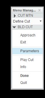
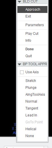
Paul here is how you add cutter com to your cut using trajectory (if your machine control will allow all 4 axis to run with cutter comp). Go to define cut then check to build cut then select approach. After that another list will pop up with several ways to enter and exit I did lead in and lead out. After you select that you can pick a line on the curve where you can lead in and out. Let me know if you have any trouble.

Jul 18, 2012
04:13 PM
- Mark as New
- Bookmark
- Subscribe
- Mute
- Subscribe to RSS Feed
- Permalink
- Notify Moderator
Jul 18, 2012
04:13 PM
Hello Matt,
I am able to program almost totally, but the cutcom wil not work. Its telling me i should theck the cutcom setup. You asked me if my machine control alows cutcom. Is this something that is set within Creo? 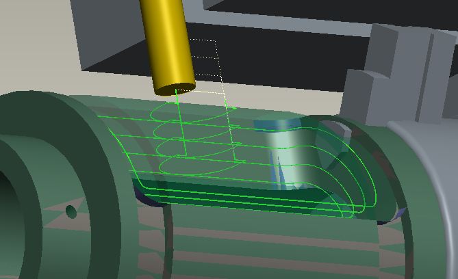
What do you select for your dirve surface? Is that a mill surface?
Jul 18, 2012
04:19 PM
- Mark as New
- Bookmark
- Subscribe
- Mute
- Subscribe to RSS Feed
- Permalink
- Notify Moderator
Jul 18, 2012
04:19 PM
Paul I was talking to some other programmers about machining with cut com using all four axis on the machine tool. And they tell me that on some controllers it is a option so if you do not have the option the controller will kick it out.I typically use the bottom edge of pie shape to drive the tool around the shape does that answer your question?
Jul 18, 2012
04:33 PM
- Mark as New
- Bookmark
- Subscribe
- Mute
- Subscribe to RSS Feed
- Permalink
- Notify Moderator
Jul 18, 2012
04:33 PM
Matt,
From all i know i have the full package avaiable in mfg inside Creo. Is this something i can check out within Creo?
What worries me is that when an accuracy is required in the model i would like to use the cutcom. For now you really helped me, thanks for that!!!
Regards,
Paul
