
Turn on suggestions
Auto-suggest helps you quickly narrow down your search results by suggesting possible matches as you type.
Showing results for
Turn on suggestions
Auto-suggest helps you quickly narrow down your search results by suggesting possible matches as you type.
Showing results for
Community Tip - When posting, your subject should be specific and summarize your question. Here are some additional tips on asking a great question. X
- Community
- Creo+ and Creo Parametric
- 3D Part & Assembly Design
- Feature Failure with Repeating Patterns
Options
- Subscribe to RSS Feed
- Mark Topic as New
- Mark Topic as Read
- Float this Topic for Current User
- Bookmark
- Subscribe
- Mute
- Printer Friendly Page
Feature Failure with Repeating Patterns
Mar 10, 2014
04:55 PM
- Mark as New
- Bookmark
- Subscribe
- Mute
- Subscribe to RSS Feed
- Permalink
- Notify Moderator
Mar 10, 2014
04:55 PM
Feature Failure with Repeating Patterns
Just recently I transfered from one division of my company to another. The first division used SolidWorks and the new division uses Creo. It has been over a decade since I used Pro/E so I am effectively a newbie. I am trying to create a structure based on a 3D array of a unit cell. Here is a screen shot of a portion of the cell created in Creo.
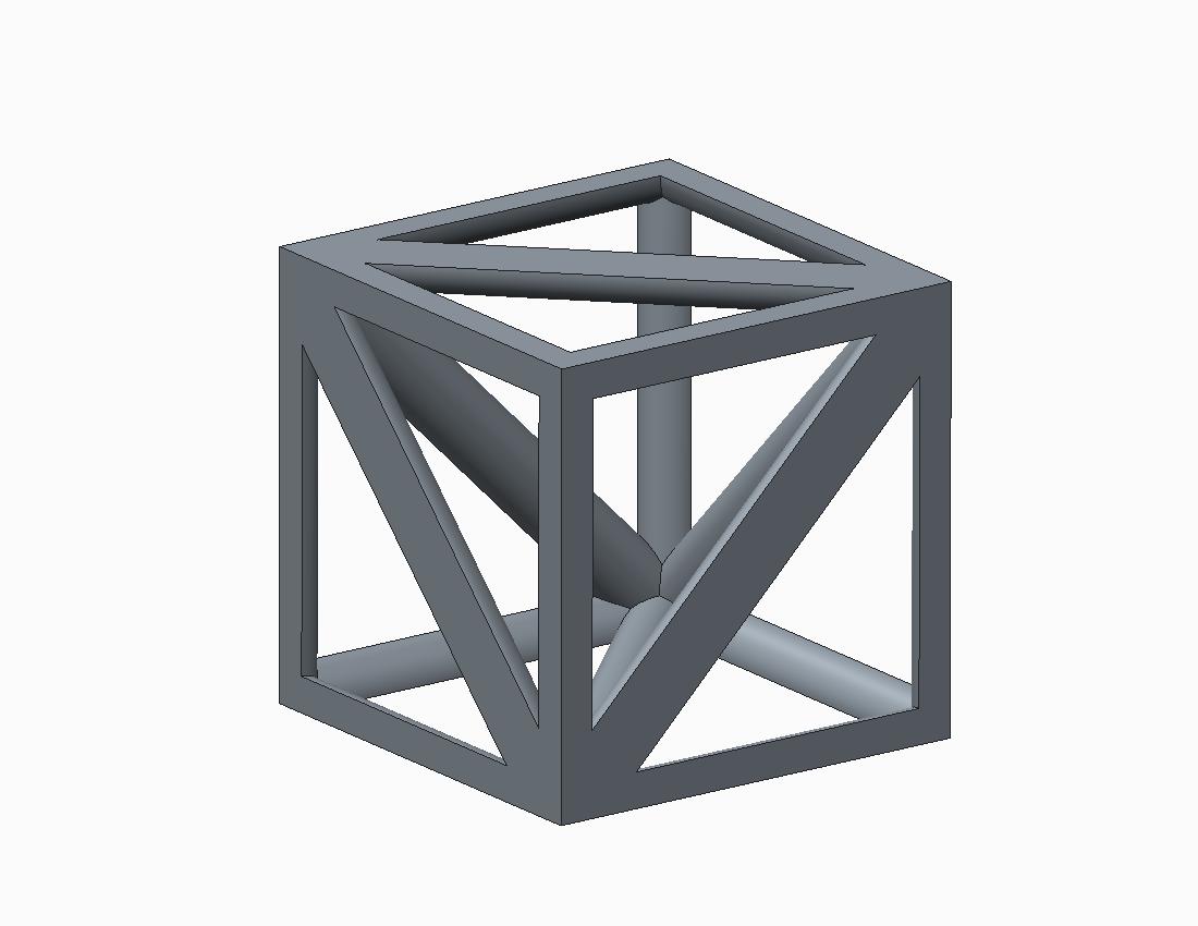
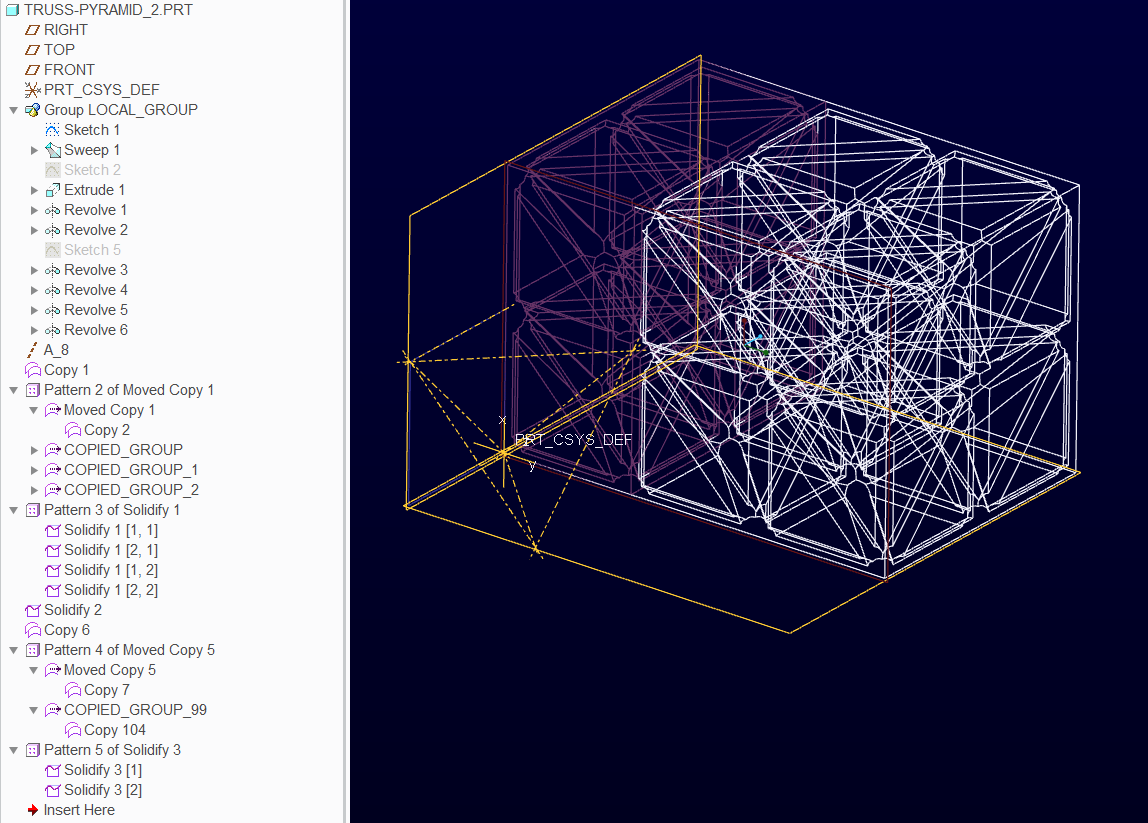
This is where I get stuck. This part must be mirrored a few times to create the actual unit cell. Since the mirror feature in Creo has no ability to revise the selections after creating it, I am trying to figure out how to pattern it with an axial pattern. When I attempt to do so, Creo gives an error stating, "Some features failed to regenerate." See the attached model.
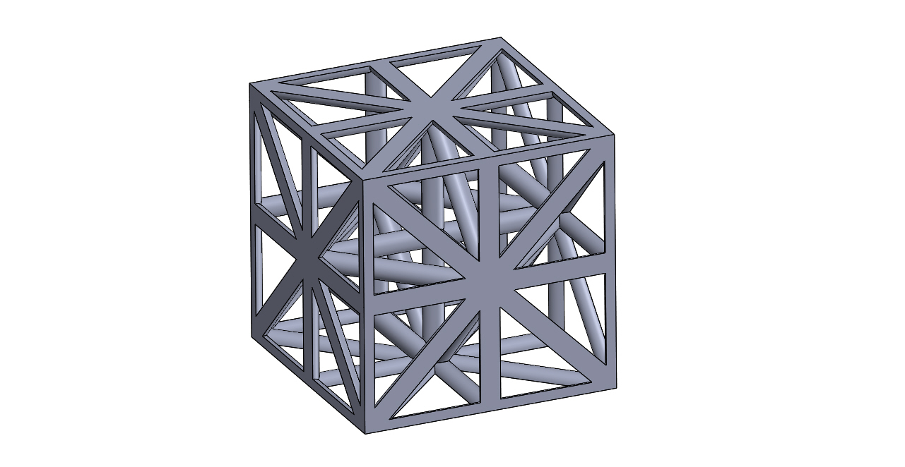
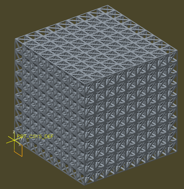
Below is a screen shot from SolidWorks showing what the unit cell should look like, and another screen shot showing what the full 3D array should look like.
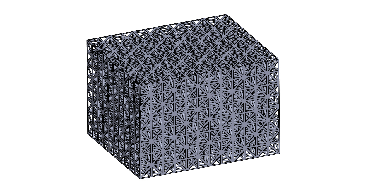
Any suggestions on how to make the patterns work?
This thread is inactive and closed by the PTC Community Management Team. If you would like to provide a reply and re-open this thread, please notify the moderator and reference the thread. You may also use "Start a topic" button to ask a new question. Please be sure to include what version of the PTC product you are using so another community member knowledgeable about your version may be able to assist.
Solved! Go to Solution.
Labels:
- Labels:
-
General
73 REPLIES 73
Mar 25, 2014
04:11 PM
- Mark as New
- Bookmark
- Subscribe
- Mute
- Subscribe to RSS Feed
- Permalink
- Notify Moderator
Mar 25, 2014
04:11 PM
Now I don't feel so bad about my 2.4ghz chip 
Thanks for posting the results, Tom!
Mar 26, 2014
02:44 PM
- Mark as New
- Bookmark
- Subscribe
- Mute
- Subscribe to RSS Feed
- Permalink
- Notify Moderator
Mar 26, 2014
02:44 PM
Tom have you run any other benchmarks on that computer?
thanks!
Matt
Mar 26, 2014
09:25 PM
- Mark as New
- Bookmark
- Subscribe
- Mute
- Subscribe to RSS Feed
- Permalink
- Notify Moderator
Mar 26, 2014
09:25 PM
Windooze 7 tells me I am "5.9" on the happy experience index
Mar 27, 2014
10:49 AM
- Mark as New
- Bookmark
- Subscribe
- Mute
- Subscribe to RSS Feed
- Permalink
- Notify Moderator
Mar 27, 2014
10:49 AM
Yeah the WEI seems to put every computer without a SSD at 5.9 (WEI uses lowest score as total).
I am wondering how the Gruman Creation machine does on other benchmarks.
Mar 27, 2014
11:06 AM
- Mark as New
- Bookmark
- Subscribe
- Mute
- Subscribe to RSS Feed
- Permalink
- Notify Moderator
Mar 27, 2014
11:06 AM
More than you probably care for.
Cine Bench 11.5
- OpenGL (fps): 100.31
- CPU (pts): 9.18
Intel Burn (GFlops)
- 4 Threads: 105.5
- All Threads: 115.0
Fritz Chess (all cores): 33.90
Node Count (single core): 1.6829
Ocus Benchmark v6.0-64bit - Creo 2.0 (M080)
- Total: 1010
- CPU: 734
- Graphics: 264
- Disk: 165
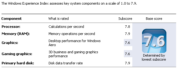
System Details
- Gruman Creations GC-i7K4
- Windows 7 Professional SP1 64-bit
- Intel Core i7-4770K CPU 3.5GHz O.C. to 4.2GHz (I thought it was 4.5, but actually only 4.2 for longevity)
- 16 GB RAM - DDR3 2133 MHz
- 240GB SATA6.0 SSD
I absolutely LOVE the SSD combined with the overclocked CPU. I've convinced our IT department to use this as the standard engineering PC going forward. 
Mar 27, 2014
11:14 AM
- Mark as New
- Bookmark
- Subscribe
- Mute
- Subscribe to RSS Feed
- Permalink
- Notify Moderator
Mar 27, 2014
11:14 AM
Mar 30, 2014
10:25 PM
- Mark as New
- Bookmark
- Subscribe
- Mute
- Subscribe to RSS Feed
- Permalink
- Notify Moderator
Mar 30, 2014
10:25 PM
I absolutely LOVE the SSD combined with the overclocked CPU. I've convinced our IT department to use this as the standard engineering PC going forward.
Nice! I ran a couple of those benchmarks, I'm a little disappointed with my single core performance, even at 4.4 Ghz.
I can't even find the Node Count one, not sure what that is.
Mar 31, 2014
07:46 AM
- Mark as New
- Bookmark
- Subscribe
- Mute
- Subscribe to RSS Feed
- Permalink
- Notify Moderator
Mar 31, 2014
07:46 AM
Mar 31, 2014
10:10 AM
- Mark as New
- Bookmark
- Subscribe
- Mute
- Subscribe to RSS Feed
- Permalink
- Notify Moderator
Mar 31, 2014
10:10 AM
Mar 31, 2014
01:10 PM
- Mark as New
- Bookmark
- Subscribe
- Mute
- Subscribe to RSS Feed
- Permalink
- Notify Moderator
Mar 31, 2014
01:10 PM
You could probably do it in one shot by using a CS, and translating and rotating as needed in a pattern table. I've done similar things in a flat pattern using a CS, but I don't see that this couldn't be done using all 3 translations and rotations, at leat for the first cube of 4.
I haven't had time to look into this, but what MIGHT be happening when he tries to mirror, is that some of the geometry goes negative. I've had those issues before (back in the day, AutoCAD told you up front to make sure all geometry was positive, probably for that reason), and had to make sure certan geometry didn't cross into negative X, Y, or Z space. I'm going to do a quick experiment by making sure none of the mirrored geometry goes negative. Then it should just pattern after that. Then maybe I can play with the ballscrew thing!
Mar 31, 2014
02:20 PM
- Mark as New
- Bookmark
- Subscribe
- Mute
- Subscribe to RSS Feed
- Permalink
- Notify Moderator
Mar 31, 2014
02:20 PM
I'm pretty sure it goes deeper than that Frank. Some of the "trim through all" and the "trim outside" features will not have boundaries in the next cell. These types of patterns are doomed to fail without very careful planning... often not worth counting on it working the 1st time. Even the lead-screw pattern of the balls failed the 1st time. I got lucky on the subsequent attempt and now easily remains parametric.
I have not used pattern tables in the past. A little tutorial or overview would be nice. Transform matrixes are sometimes quite a handful in the standard pattern dialog when you try and use more than one direction. it also seems to go into cumulative error mode from time to time and you have to start over. Something about the previous attempt gets stuck in the matrix but inaccessible.
Mar 31, 2014
03:27 PM
- Mark as New
- Bookmark
- Subscribe
- Mute
- Subscribe to RSS Feed
- Permalink
- Notify Moderator
Mar 31, 2014
03:27 PM
What I was going to try was making a box out of surfaces, using sweeps for all the cylinrical beams, then using the box to trim all the outer ones. So that it was all self-contained before I did anything else.
But, it's all theoretical for now so my theory may just blow up in my face (as happens often enough!).
Mar 13, 2014
12:59 PM
- Mark as New
- Bookmark
- Subscribe
- Mute
- Subscribe to RSS Feed
- Permalink
- Notify Moderator
Mar 13, 2014
12:59 PM
Looks to me like you could pattern the cube 4 times @ 90 deg around a vertical axis, say, the back left edge, then pattern the new pattern of 4 about a horizontal axis 2 @ 180 deg. Then pattern that into your block. That way you don't have to deal with those maddening mirror issues, and have full adjustability.
Mar 31, 2014
06:37 PM
- Mark as New
- Bookmark
- Subscribe
- Mute
- Subscribe to RSS Feed
- Permalink
- Notify Moderator
Mar 31, 2014
06:37 PM
Wow, there sure seems to be some buggy behavior in there. I tried a coupe things and at first I thought the external cut i used to trim the truss diameter was causing issues, and it was, so I fixed that to not use any cuts on the outside. The first 2 mirrors worked fine, so I got the bottom 4, tried to mirror that and it bombed, with a couple features in the group failing. The pattern worked a little better, but still a few non-regenerated features.
What Pro/E SHOULD do is simply mirror the GEOMETRY, and not need all the baggage of copying all the internal sketches, etc.
Got a few tricks still. 
Mar 31, 2014
07:27 PM
- Mark as New
- Bookmark
- Subscribe
- Mute
- Subscribe to RSS Feed
- Permalink
- Notify Moderator
Mar 31, 2014
07:27 PM
You mean copy the geometry as dumb features like most others do? Yes, I agree. But solids don't work that way in Creo.
Patterns have been extremely buggy. It is suppose to be fixed as of M090 but I am willing to bet this will always be problematic. Had one blow up today that simply didn't make sense. Flipped a datum plane and all worked fine... go figure!
Apr 01, 2014
09:48 AM
- Mark as New
- Bookmark
- Subscribe
- Mute
- Subscribe to RSS Feed
- Permalink
- Notify Moderator
Apr 01, 2014
09:48 AM
Gonna try a couple tricks, such as making the original cube, copying all solid surfs, and then translating and pasting that and a solidify.
Well, at least we have a lot more tools and the ability to pattern via an axis or direction. Remember when you had to create a radial pattern by creating a radial datum thru axis on the fly, and all that nonsense. So, the interface is better, if not the code behind it.
I think Pro/E needs a total re-write to clean up the bugs, not wasted time on whiz-bang GUI's that are actually counter-productive, but maybe that's just me.........(or not)!
Apr 01, 2014
10:46 AM
- Mark as New
- Bookmark
- Subscribe
- Mute
- Subscribe to RSS Feed
- Permalink
- Notify Moderator
Apr 01, 2014
10:46 AM
Hi Jeff,
My preferred solution for something like this is to make a surface copy, pattern that, then solidify.
If you repeat the feature creation you will incur a significant overhead as features need to recalculate their intersections with existing geometry as well as adding their parameters to the file.
A surface copy has minimal parameters associated with it and the intersection calculations where one feature crosses another have already been done.
After copying use the paste special to apply transformation parameters then pattern the transformed surface. A ref pattern solidify will then complete the solid part.
regards
Phil
Apr 01, 2014
10:57 AM
- Mark as New
- Bookmark
- Subscribe
- Mute
- Subscribe to RSS Feed
- Permalink
- Notify Moderator
Apr 01, 2014
10:57 AM
Remember though that surfaces require merging. Therefore the copies require merging to each other. That is what is taking up all that time in the solid model patterns. If you were not going to bother merging the surface quilts in the matrix pattern, you might as well make it a single solid cell and assemble them at a next level with the pattern. We already know that this is very efficient.
Philip, welcome to the forum.
Also, please do not attach in RAR format. I do not allow any rar decoding on my computer.
Apr 01, 2014
11:56 AM
- Mark as New
- Bookmark
- Subscribe
- Mute
- Subscribe to RSS Feed
- Permalink
- Notify Moderator
Apr 01, 2014
11:56 AM
Here it is in zip format.
The model is solid but incurs fewer intersection calculations by solidifying the transformed quilt than patterning all the features.
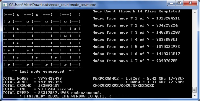
To go from 3x3x3 to 9x9x9 takes 14 seconds using 2.4Gz i7 3840QM processor. This appears much quicker than some of the other quoted times.
Regards
Phil
Apr 01, 2014
12:09 PM
- Mark as New
- Bookmark
- Subscribe
- Mute
- Subscribe to RSS Feed
- Permalink
- Notify Moderator
Apr 01, 2014
12:09 PM
I'm doing that, and have had some failures doing geometry patterns. Unfortunately I have WF5/creo, and so probably can't open your model.
I'd call this a serious bug. There's no reason we should have to jump through hoops like this, especially since it seems like Solidworks can easily do this pattern.
Apr 01, 2014
12:19 PM
- Mark as New
- Bookmark
- Subscribe
- Mute
- Subscribe to RSS Feed
- Permalink
- Notify Moderator
Apr 01, 2014
12:19 PM
Phil, your cell is not complete. The cell you are using is duplicated 8 times before the matrix is generated.
Apr 01, 2014
12:36 PM
- Mark as New
- Bookmark
- Subscribe
- Mute
- Subscribe to RSS Feed
- Permalink
- Notify Moderator
Apr 01, 2014
12:36 PM
Interesting technique. You start with a solid so the copied surfaces are merged. And you reference-pattern the solidify. ( I wonder why that couldn't be part of the 1st pattern?)
I can see how that takes care of a lot of the calculations in the intersecting -sticks- method.
Apr 01, 2014
12:40 PM
- Mark as New
- Bookmark
- Subscribe
- Mute
- Subscribe to RSS Feed
- Permalink
- Notify Moderator
Apr 01, 2014
12:40 PM
If you count the cells you will see its a 9x9x9. The first 9x9 layer is copied and duplicated 8 times.
Apr 01, 2014
12:51 PM
- Mark as New
- Bookmark
- Subscribe
- Mute
- Subscribe to RSS Feed
- Permalink
- Notify Moderator
Apr 01, 2014
12:51 PM
Understood, but the cell is defined as 8 of the 1st group you created (progressive mirrors). Then the matrix is applied.
From the original post, this is the cell:

Apr 01, 2014
01:11 PM
- Mark as New
- Bookmark
- Subscribe
- Mute
- Subscribe to RSS Feed
- Permalink
- Notify Moderator
Apr 01, 2014
01:11 PM
Yup, great catch Antonius! I just looked at it and didn't zoom in because it wanted to force me to download it, which I will not do just to view something.
So, my question to the OP (Jeff) then is if the cell of 4 is never broken down, why not simply create that as your initial geometry, and pattern that? This way, you don't have multiple patterns and mirrors, all buried inside each other and just asking for trouble.
Apr 01, 2014
01:38 PM
- Mark as New
- Bookmark
- Subscribe
- Mute
- Subscribe to RSS Feed
- Permalink
- Notify Moderator
Apr 01, 2014
01:38 PM
I am certain this has to pertain to the chosen method, Frank. Indeed that is a valid observation.
This is what is included in Philip's model...
Apr 01, 2014
01:51 PM
- Mark as New
- Bookmark
- Subscribe
- Mute
- Subscribe to RSS Feed
- Permalink
- Notify Moderator
Apr 01, 2014
01:51 PM
Thanks brotha! Man, PTC REALLY need to come up with a (of course optional/more $$) module that let's users at least OPEN more advanced version models, if only to see what the model tree looks like. I understand not letting people who have let their maintenance lapse get full access to the models made in newer versions, but in my case we HAVE maintenance yet are for some reason sticking to the worst version of creo. I'd like to be able to at least look at your models. Gah!
I'm playing with pattern tables, and yes, you can pattern using a CS. This is EXTREMELY powerful as you have 6 different dimensions you can use, and are not limited to a 2D pattern. Even if you don't use a CS, we should not be limited to 2D patterns, we should be able to pick 3 directions on a direction pattern, even if they're normal to one another (default datums).
I'll post up a CS-driven pattern table part shortly.
Apr 01, 2014
02:10 PM
- Mark as New
- Bookmark
- Subscribe
- Mute
- Subscribe to RSS Feed
- Permalink
- Notify Moderator
Apr 01, 2014
02:10 PM
Looking forward to it, Frank.
Apr 01, 2014
02:15 PM
- Mark as New
- Bookmark
- Subscribe
- Mute
- Subscribe to RSS Feed
- Permalink
- Notify Moderator
Apr 01, 2014
02:15 PM
Ok, here goes:
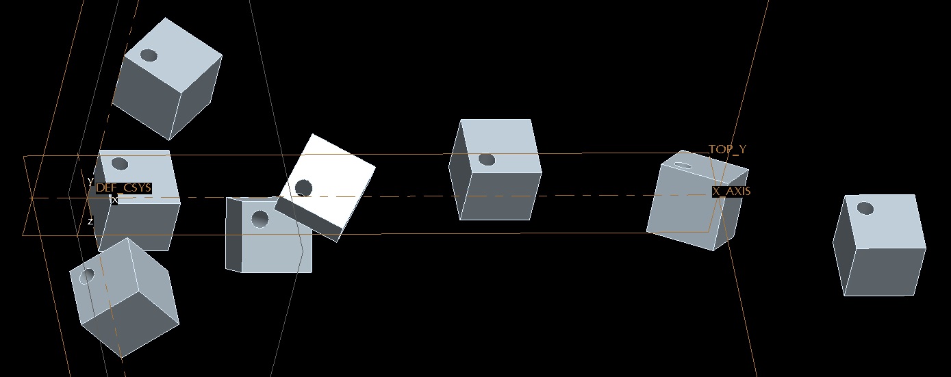
I'd played with CS-driven tables before, just not all 6 DOF at once! Good to know it can be done. Pattern tables are very powerful, if cumbersome. In some cases, when you need to change a family instance to have 6 bolt holes in a pattern instead of 8, this is how you need to do it, instead of suppressing one pattern and resuming another. This prevents fasteners (and other parts) constrained at assembly from failing, as they would if you simply turned one pattern off and the other on.
Apr 01, 2014
02:37 PM
- Mark as New
- Bookmark
- Subscribe
- Mute
- Subscribe to RSS Feed
- Permalink
- Notify Moderator
Apr 01, 2014
02:37 PM
That's how it's done!
Thanks Frank!
