
Turn on suggestions
Auto-suggest helps you quickly narrow down your search results by suggesting possible matches as you type.
Showing results for
Turn on suggestions
Auto-suggest helps you quickly narrow down your search results by suggesting possible matches as you type.
Showing results for
Community Tip - Learn all about the Community Ranking System, a fun gamification element of the PTC Community. X
- Community
- Creo+ and Creo Parametric
- 3D Part & Assembly Design
- Feature Failure with Repeating Patterns
Options
- Subscribe to RSS Feed
- Mark Topic as New
- Mark Topic as Read
- Float this Topic for Current User
- Bookmark
- Subscribe
- Mute
- Printer Friendly Page
Feature Failure with Repeating Patterns
Mar 10, 2014
04:55 PM
- Mark as New
- Bookmark
- Subscribe
- Mute
- Subscribe to RSS Feed
- Permalink
- Notify Moderator
Mar 10, 2014
04:55 PM
Feature Failure with Repeating Patterns
Just recently I transfered from one division of my company to another. The first division used SolidWorks and the new division uses Creo. It has been over a decade since I used Pro/E so I am effectively a newbie. I am trying to create a structure based on a 3D array of a unit cell. Here is a screen shot of a portion of the cell created in Creo.
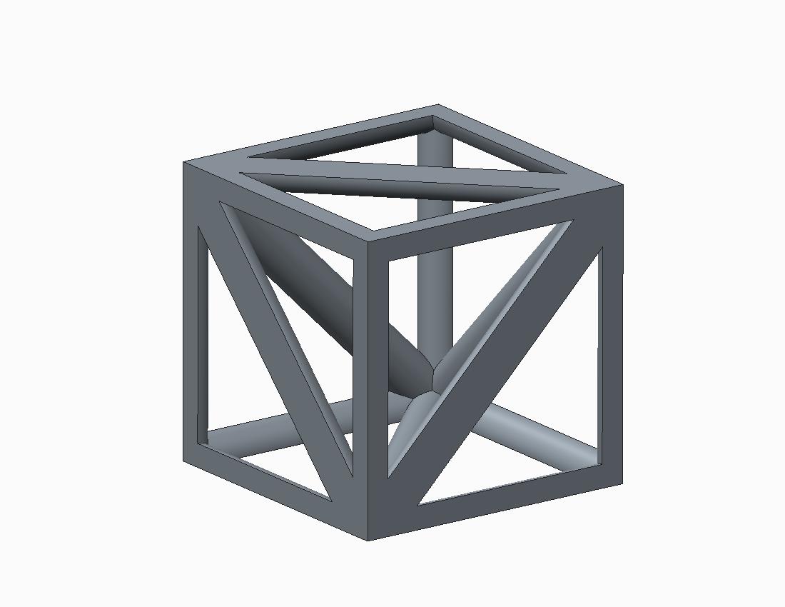
This is where I get stuck. This part must be mirrored a few times to create the actual unit cell. Since the mirror feature in Creo has no ability to revise the selections after creating it, I am trying to figure out how to pattern it with an axial pattern. When I attempt to do so, Creo gives an error stating, "Some features failed to regenerate." See the attached model.
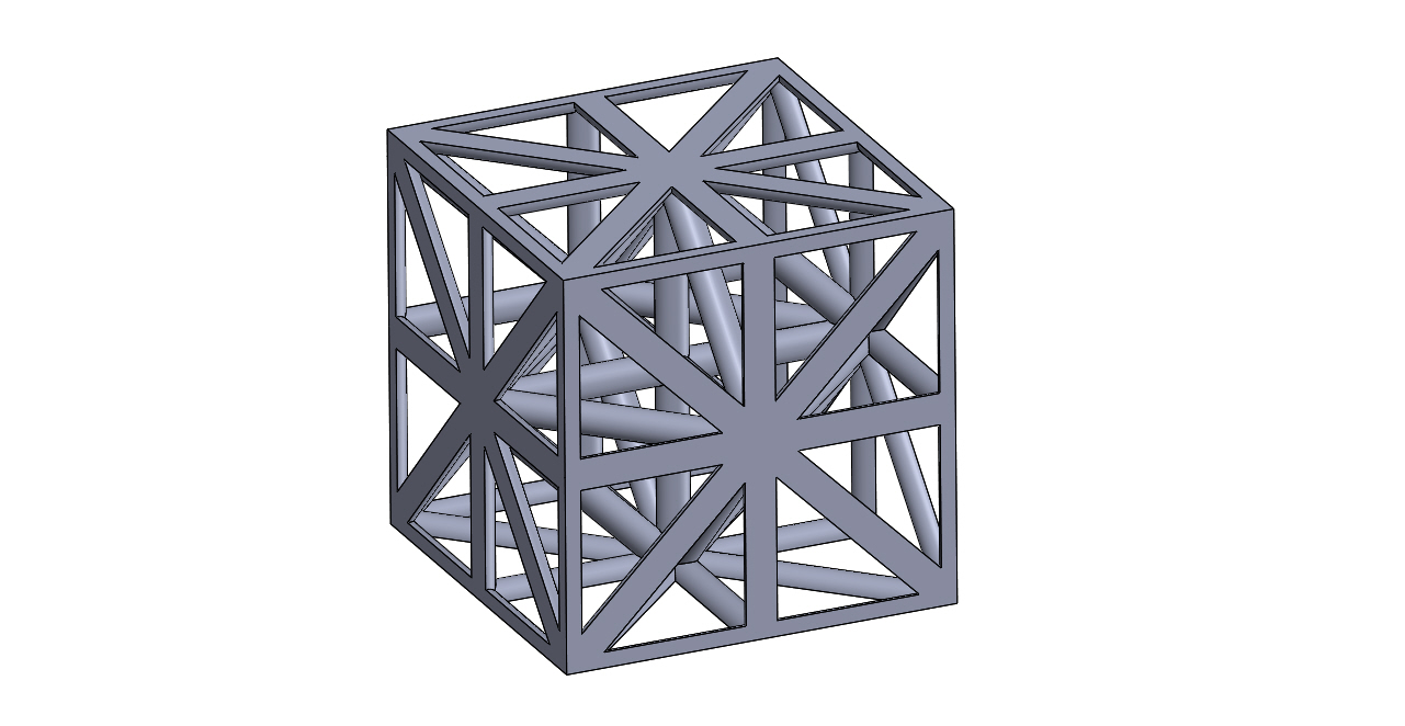
Below is a screen shot from SolidWorks showing what the unit cell should look like, and another screen shot showing what the full 3D array should look like.
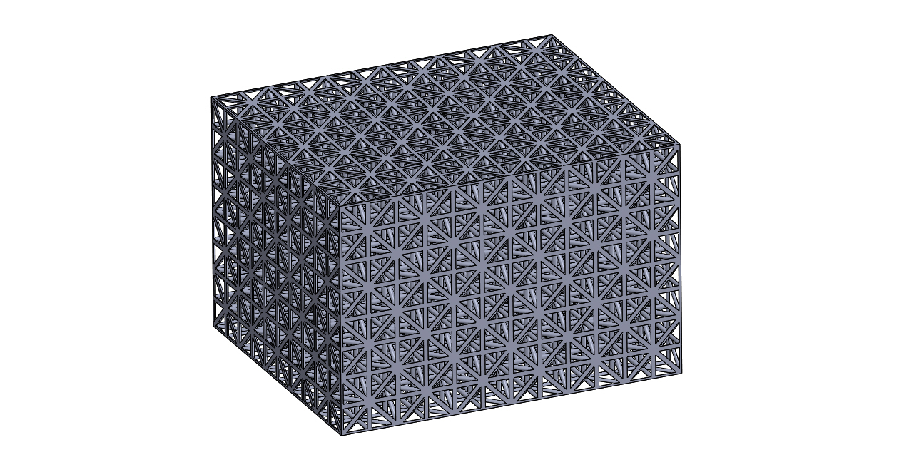
Any suggestions on how to make the patterns work?
This thread is inactive and closed by the PTC Community Management Team. If you would like to provide a reply and re-open this thread, please notify the moderator and reference the thread. You may also use "Start a topic" button to ask a new question. Please be sure to include what version of the PTC product you are using so another community member knowledgeable about your version may be able to assist.
Solved! Go to Solution.
Labels:
- Labels:
-
General
73 REPLIES 73
Apr 01, 2014
02:51 PM
- Mark as New
- Bookmark
- Subscribe
- Mute
- Subscribe to RSS Feed
- Permalink
- Notify Moderator
Apr 01, 2014
02:51 PM
Anytime brotha!
Now, to play with that other one until I'm happy with it.
Think I'm going to do it as a surfaced "cell" (merges, etc.), then pattern that, then reference pattern a solidify.
That should provide a solid, but pattern better and faster.
Apr 05, 2014
12:37 AM
- Mark as New
- Bookmark
- Subscribe
- Mute
- Subscribe to RSS Feed
- Permalink
- Notify Moderator
Apr 05, 2014
12:37 AM
I tested Philip's method some more and it still slows down significantly after you create the larger matrix even if you use a similar technique to create the complete cell. I will need to see what a full 9x9x9 matrix does with these new revelations.
However, it is a very interesting technique and it does remove a lot of the failures you would otherwise get.
There are some intricacies in developing this method. Technically it creates a solid - copies all the solid surfaces - patterns the copied surface quilt - solidify the original copy - reference pattern the solidify. And yes, you can nest this.
As for Frank's help in the Table pattern, I always had trouble figuring out how to pattern a 2x2x2 transformation matrix where the master is mirrored in all directions through rotations. I finally got it to work and certainly worth sharing in this very relevant thread.
The technique for a 3D matrix combines the CSYS, datum planes, and features into a single group (sub-cell). CS1 is offset to CS0 at 0,0,0,r0,r0,r0 which provides the pattern with rotation and translation vectors. I edited d0, d1, and d2 to RX, RY, and RZ to make the table more understandable.
The idea is that one corner of the cell is defined, very much like the sub-cell in the original post and the first feature Philip made.
In one go, all 8 corners can be patterned with the table method. You simply click (and add with CTRL) the 3x CS1 rotation vectors to add them to the list.
Next you edit the table as shown: ...don't ask me the logic; it just works 
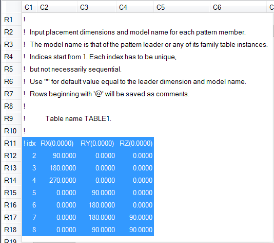
I put numeric identifiers on the model to show the order in which the pattern was created. This should follow a sequence of rotation as noted in the file. the color coding is my own file that helped me follow the sequence. RGBVCYP& whatever hi-vis green is.
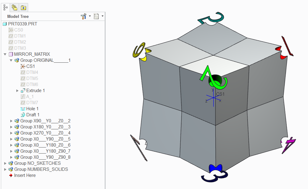
Of course, everything still relates to the original sub-cell. Just play with some of the feature in the 1st group to get some interesting results.
Thanks again, Frank. Without your file I would have never got this! 
The attached model is Creo 2.0 full version.
Apr 05, 2014
01:35 AM
- Mark as New
- Bookmark
- Subscribe
- Mute
- Subscribe to RSS Feed
- Permalink
- Notify Moderator
Apr 05, 2014
01:35 AM
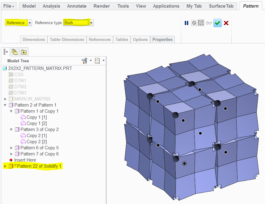
Now this I didn't know...
if you have a nested pattern (directional X, Y, &Z), you can select the full set using the BOTH (groups and feature) option:
Apr 05, 2014
03:23 AM
- Mark as New
- Bookmark
- Subscribe
- Mute
- Subscribe to RSS Feed
- Permalink
- Notify Moderator
Apr 05, 2014
03:23 AM
Okay, time to concede...
12 minutes for a 9x9x9 at 1586 features to regenerate.
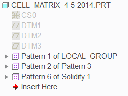
I used the technique for creating the cell from the quarter sub-cell... (pattern 1 corner 8x using Table)
Then a pair of nested direction patterns of a Copy feature - "all solid surfaces" making individual surface quilt cells in the matrix.
The a single solidify reference pattern that covers all the patterned quilt in one go using "BOTH" groups and features.
Part level variables:
CELL=2
TUBE=CELL/10
MATRIX_X=2
MATRIX_Y=2
MATRIX_Z=2
So now it grows from one corner and the tube is a ratio of the cell size.
Thanks Philip!
Thanks Frank!
Thanks Jeff!
Apr 05, 2014
01:05 PM
- Mark as New
- Bookmark
- Subscribe
- Mute
- Subscribe to RSS Feed
- Permalink
- Notify Moderator
Apr 05, 2014
01:05 PM
I messed with this one a little, I'm not sure what CELL and TUBE are. Also loading this posted model, cell=1 and tube=cell/15 versus the 2 and /10 shown above (again I'm not sure what these are defining).
What also seems odd is when I did the previous borg version, after the long regen, spinning it around the screen was no problem at all, where as this version has the fast regen time, but seems much slower to spin it around after.
Apr 05, 2014
02:57 PM
- Mark as New
- Bookmark
- Subscribe
- Mute
- Subscribe to RSS Feed
- Permalink
- Notify Moderator
Apr 05, 2014
02:57 PM
I defined the cell as in the size of the full matrixed sub-structure (pattern 1). So the beginning feature is driven by CELL/2 relations for the features.
Tube is the diameter of the tubes, rods, or whatever you want to call them. I found it easiest to manage them as a ratio to the cell size.
Interesting observation in the graphics performance. I am not sure what that would happened unless for some reason the graphics engine is still maintaining the quilt definitions.
Maybe we have peeked the interest of some PTC engineers to review these models and what is going on in the background. We have certainly provided enough models for some serious investigation.
Apr 07, 2014
09:47 AM
- Mark as New
- Bookmark
- Subscribe
- Mute
- Subscribe to RSS Feed
- Permalink
- Notify Moderator
Apr 07, 2014
09:47 AM
Nice work Antonius, as always! 
Apr 04, 2014
05:08 PM
- Mark as New
- Bookmark
- Subscribe
- Mute
- Subscribe to RSS Feed
- Permalink
- Notify Moderator
Apr 04, 2014
05:08 PM
Interesting idea, I'll try it.
Apr 04, 2014
05:21 PM
- Mark as New
- Bookmark
- Subscribe
- Mute
- Subscribe to RSS Feed
- Permalink
- Notify Moderator
Apr 04, 2014
05:21 PM
Thanks for all the input and ideas on this issue. I contacted technical support and the representative I spoke with seemed to think that this is a bug. He tried the Geometry Pattern and spaced the instances 2.51 mm apart, so that they have just a little space between them. When he did so they worked fine, even though they do not work correctly when touching. He forwarded the issue on to R&D, so it will be interesting to hear their response.
In the mean time maybe one of the alternate techniques mentioned here will lead to a robust model. Then again, I might just beg a plead with management to let me model this part with SolidWorks. Some might say that SolidWorks creates patterns with dumb solids. After wrestling with Creo off and on for four weeks to create this part, those dumb solids are looking a whole lot like smart solids. 
Apr 04, 2014
07:38 PM
- Mark as New
- Bookmark
- Subscribe
- Mute
- Subscribe to RSS Feed
- Permalink
- Notify Moderator
Apr 04, 2014
07:38 PM
Jeff Wickham wrote:
After wrestling with Creo off and on for four weeks to create this part, those dumb solids are looking a whole lot like smart solids.
So, what are you trying to do? Aren't there multiple solutions in this thread?
Apr 08, 2014
11:14 AM
- Mark as New
- Bookmark
- Subscribe
- Mute
- Subscribe to RSS Feed
- Permalink
- Notify Moderator
Apr 08, 2014
11:14 AM
By my comment I certainly did not intend to detract from the efforts people have expended on this issue. There are indeed multiple solutions in this thread, ones that are marvels of creativity and skill. I am humbled by the generous hours people have spent on this issue, and I am truly grateful.
My comment was solely directed at the software, not the users or the solutions presented here. It seems to me that Creo needs a robust way to create these patterns with only a minimum amount of time and skill. It has been amazing to watch such experienced users collaborate and come up with unique ways to tackle this part. My point is that ideally the software should contain capability so that an almost new user working alone can create these patterns in just a couple of minutes. Maybe once PTC gets the bugs fixed with the Geometry Pattern feature it will provide that sort of functionality.
Apr 08, 2014
12:24 PM
- Mark as New
- Bookmark
- Subscribe
- Mute
- Subscribe to RSS Feed
- Permalink
- Notify Moderator
Apr 08, 2014
12:24 PM
True, what seem like relatively simple patterns fail quite easily. I'm still wondering how parametric do you need it? One method I didn't try was to draw the base element then export, import and pattern that.
I'm also happy that Tom U stepped in with some input from his performance machine, there is a (in my opinion) huge lack of power computing discussions in these forums.
Apr 08, 2014
12:52 PM
- Mark as New
- Bookmark
- Subscribe
- Mute
- Subscribe to RSS Feed
- Permalink
- Notify Moderator
Apr 08, 2014
12:52 PM
Agreed! Well-said!
Apr 08, 2014
01:27 PM
- Mark as New
- Bookmark
- Subscribe
- Mute
- Subscribe to RSS Feed
- Permalink
- Notify Moderator
Apr 08, 2014
01:27 PM
I think PTC's solution is Creo Elements Direct modeling. Now that they own Co-Create, this is -exactly- what made that package so powerful. It maintains that fine line between parametric and geometry.
- « Previous
- Next »
