
Turn on suggestions
Auto-suggest helps you quickly narrow down your search results by suggesting possible matches as you type.
Showing results for
Turn on suggestions
Auto-suggest helps you quickly narrow down your search results by suggesting possible matches as you type.
Showing results for
Community Tip - Have a PTC product question you need answered fast? Chances are someone has asked it before. Learn about the community search. X
- Community
- Creo+ and Creo Parametric
- 3D Part & Assembly Design
- Flexible Modeling
Options
- Subscribe to RSS Feed
- Mark Topic as New
- Mark Topic as Read
- Float this Topic for Current User
- Bookmark
- Subscribe
- Mute
- Printer Friendly Page
Flexible Modeling
Jul 22, 2011
12:36 PM
- Mark as New
- Bookmark
- Subscribe
- Mute
- Subscribe to RSS Feed
- Permalink
- Notify Moderator
Jul 22, 2011
12:36 PM
Flexible Modeling
You can read the Desktop Product Focus of the Month here also authored by Scot Zundel and you can also read the Enterprise Product Focus of the Month here and the Enterprise Tip of the Month here authored by John Peng.
| PTC Technical Specialists Newsletter - Summer 2011 |
Desktop Tip of the Month : Flexible Modeling |
|---|
The Flex Modeling Extension provides a subset of direct modeling techniques within Creo Parametric to enable AnyMode Modeling to CAD designers and engineers. It is a set of geometry-based editing tools that do not leverage or impact underlying features. This means that the user does not need to understand the feature history or design intend to edit geometry or change any design intend that may be present – truly maintaining the history but adding direct edits to a parametric model. The Flex Moves are stored as parametric features that can be changed like other parametric.
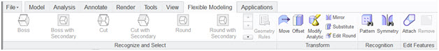
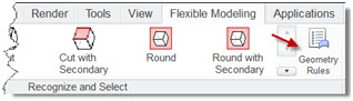
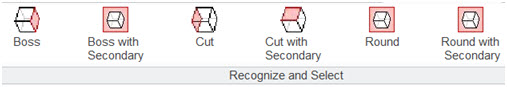
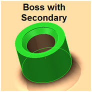
There are 4 sections on the Flexible Modeling tab. The Recognize and Select section which helps users quickly select geometry such as a boss, a cut, and even a boss with secondary geometry like a round. The commands in the Transform section range from a simple move of a face to more the complex edits such as a substitution of one surface shape for another unrelated shape. The Recognition on the right hand side identifies patterns and symmetry present in the model. Lastly the Edit Features section provides different solutions about attaching or removing geometry.
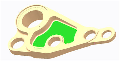
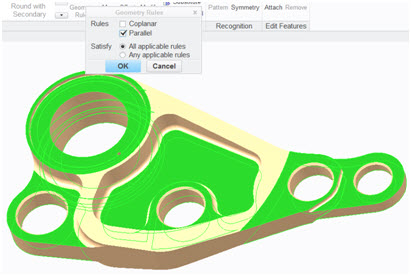
Using the selection commands, a user can quickly select the geometry based on shape or geometry rules such as parallel surfaces, rounds of equal radius, and coaxial holes. For example to select all parallel surfaces to the surface shown highlighted in green, select the geometry rules, and check the parallel option.
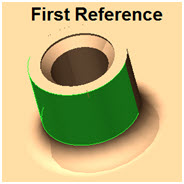
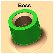
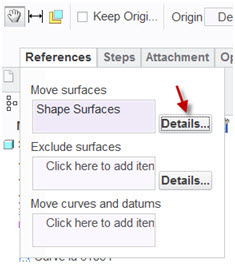
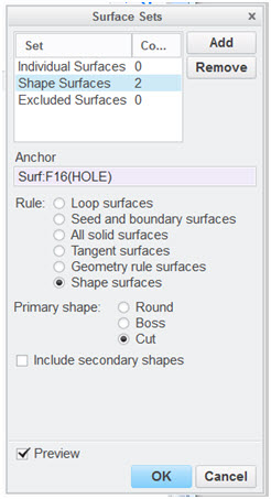
Another selection method is shape recognition such as a boss, cut or round. Start by selecting geometry such as a surface and then the corresponding type.
Multiple shapes can be included or excluded with the Ctrl key on the keyboard as well as additional options are available in the dashboard to make selection of geometry easier.
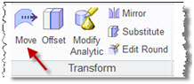
TRANSFORM
There are many transform commands; I will focus on the Move command because it will likely generate the most interest from customers.
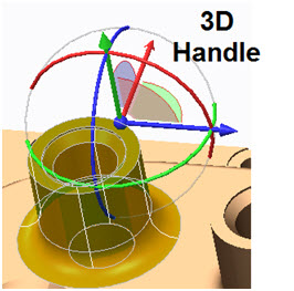
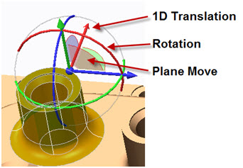
There are 3 types of move options: move with dragger; move by dimension; and move by assembly. Move with dragger enables users to translate and rotate the geometry in the X, Y, and Z directions via a 3D handle. The arrows enable 1D translation, the semi-circles enable 1D rotation, the fans between the arrows enable 2D translation in that plane, and the ball allows 3D translation.
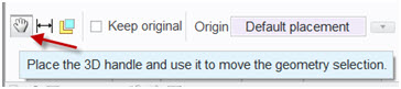
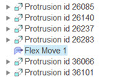
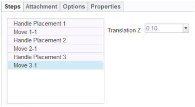
After the move command is started and the geometry selected, a default handle is automatically activated providing intuitive visual feedback. If there is a need to move the geometry other than the default placement of the 3D handle, users can select existing geometry or datums to control moves. Also, there is an option to create datum features on the fly to create a movement reference. An example move could be, tranlate 0.5in via the default X-arrow, select an edge from the geometry for a 10 degree Y-axis rotation, and create a datum plane on the fly for a plane move. The steps of a move are under the Steps tab where the handle placements and moves can be reviewed and edited. Mutliple steps are included in 1 move to reduce complexity of the number of move in the model tree.
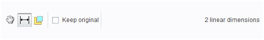
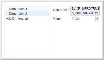
Move by dimension enables the user to create a dimensioning scheme to move the geometry with an angular dimension or up to 3 linear dimensions. The first movement reference must be a ground reference and the second reference must be part of the selected reference to move. For example, the ground reference could be a mating surface and the second reference could be the central axis on a boss. There is no 3D handle in this process, but there are drag handles similar to those when placing other features such as a hole.

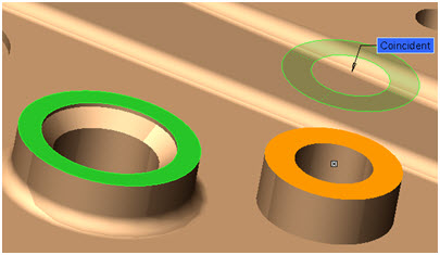
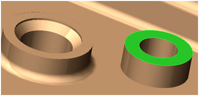
The last move option is move by assembly which follows the typical assembly process via assembly constraints.
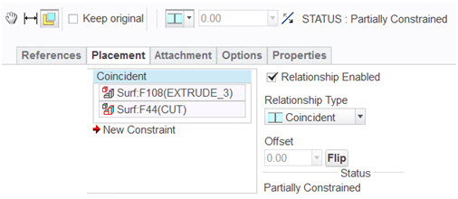
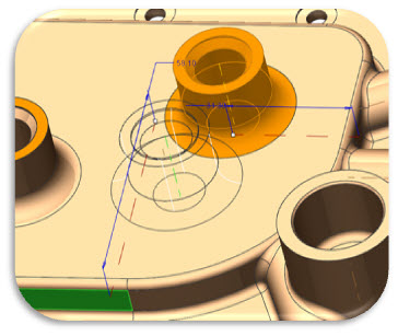
In this example, the top of boss on the right side was lowered to be coincident with the boss on the left side. Multiple constraints can be used on the move to achieve the desired effect. Those familiar with assembly constraints should be able to learn this command very quickly.
Recognition
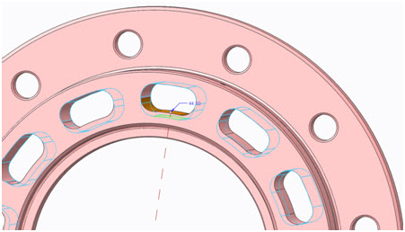
One of the problems with non-native CAD data is the difficulty of making changes. With flex modeling extension, non-native data with linear or radial patterns can be recognized and modified. In this example, the cut selected in green is 1 of 12 members in a radial pattern on this part.
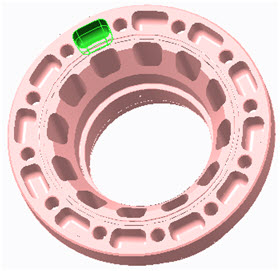
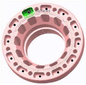
Now these pattern members can be modified simultaneously with the flexible modeling tools.
The Flex Modeling Extension provides a small yet effective set of direct modeling capabilities within a parametric environment without losing the benefits of parametric design.
This thread is inactive and closed by the PTC Community Management Team. If you would like to provide a reply and re-open this thread, please notify the moderator and reference the thread. You may also use "Start a topic" button to ask a new question. Please be sure to include what version of the PTC product you are using so another community member knowledgeable about your version may be able to assist.
0 REPLIES 0
