
Turn on suggestions
Auto-suggest helps you quickly narrow down your search results by suggesting possible matches as you type.
Showing results for
Turn on suggestions
Auto-suggest helps you quickly narrow down your search results by suggesting possible matches as you type.
Showing results for
Community Tip - New to the community? Learn how to post a question and get help from PTC and industry experts! X
- Community
- Creo+ and Creo Parametric
- 3D Part & Assembly Design
- HELP ADDING DRAFT
Options
- Subscribe to RSS Feed
- Mark Topic as New
- Mark Topic as Read
- Float this Topic for Current User
- Bookmark
- Subscribe
- Mute
- Printer Friendly Page
HELP ADDING DRAFT
Oct 03, 2012
08:35 AM
- Mark as New
- Bookmark
- Subscribe
- Mute
- Subscribe to RSS Feed
- Permalink
- Notify Moderator
Oct 03, 2012
08:35 AM
HELP ADDING DRAFT
Hello! I am having trouble adding drat to the left side of the "g" feature on this part. I use this same extrusion on other parts and it drafted fine. I don't know what I am doing different... I need to add 2° draft in the same direction as the right side of the "g". Can anyone tell me what the problem is? I can add radii or change the size slightly if that helps???
This thread is inactive and closed by the PTC Community Management Team. If you would like to provide a reply and re-open this thread, please notify the moderator and reference the thread. You may also use "Start a topic" button to ask a new question. Please be sure to include what version of the PTC product you are using so another community member knowledgeable about your version may be able to assist.
Solved! Go to Solution.
Labels:
- Labels:
-
General
1 ACCEPTED SOLUTION
Accepted Solutions
Oct 03, 2012
10:52 AM
- Mark as New
- Bookmark
- Subscribe
- Mute
- Subscribe to RSS Feed
- Permalink
- Notify Moderator
Oct 03, 2012
10:52 AM
Hi Colette...
Depending upon your geometry, drafts can sometimes be tricky. Sure enough, in this case your geometry is causing the problem. Per the PTC Help Guide on drafts: You can draft only the surfaces that are formed by tabulated cylinders or planes. What this is saying (albeit cryptically) is that spline surfaces or complex curvatures may cause problems requiring alternate techniques to resolve.
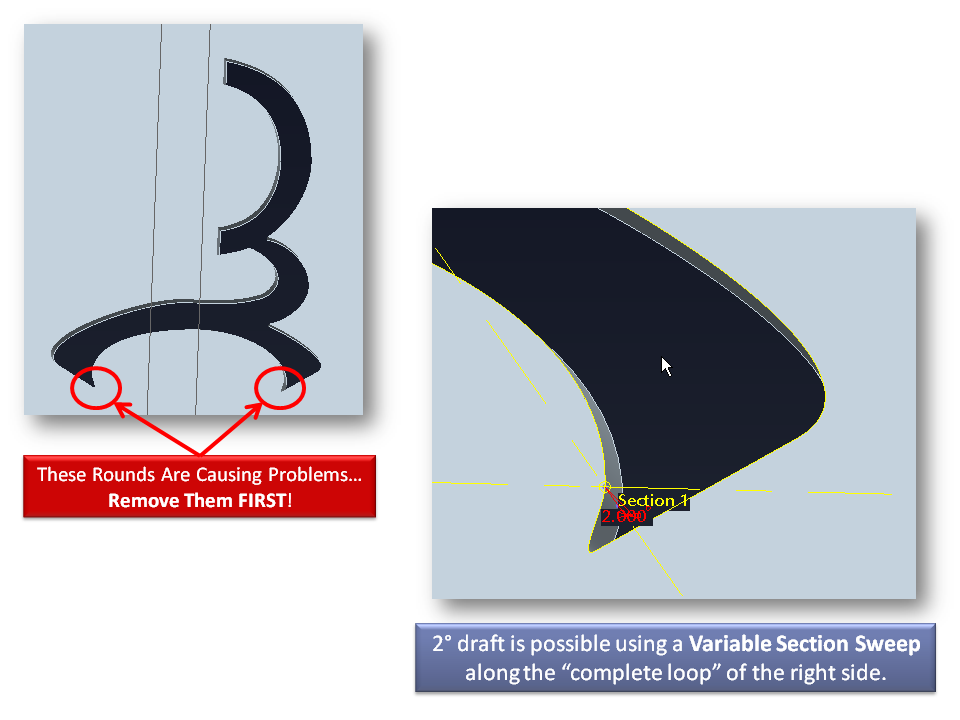
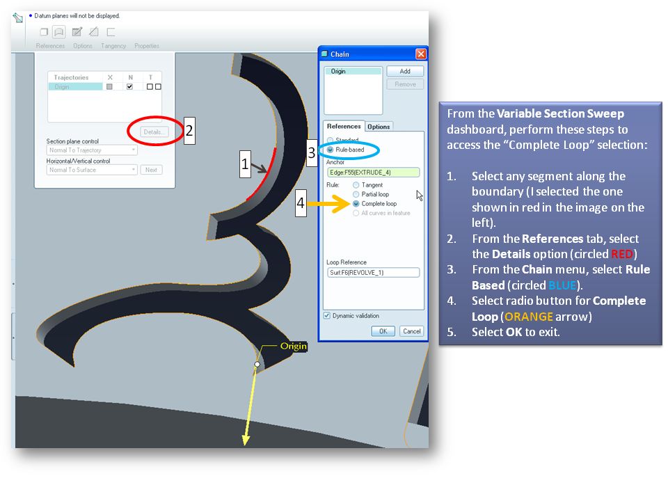
I managed to draft the surfaces you were having problems with by using a Variable Section Sweep. First, I had to remove the micro-rounds in the corners (see slides below). I used the Complete Loop option of a Variable Section Sweep (VSS) to achieve this. I detailed the steps to accessing this option below.
Your geometry is the real culprit here, though. I realize you're trying to use a stylized piece of geometry- like a logo. These are often very "swooshy" and artistic looking with lots of curves and splines and conics. From experience I can tell you Creo can't always handle drafts on these surfaces due to the self-intersecting nature of those drafts. for example, in those tight "turns" (especially the ones circled in red below featuring the rounds), drafting becomes very tough.
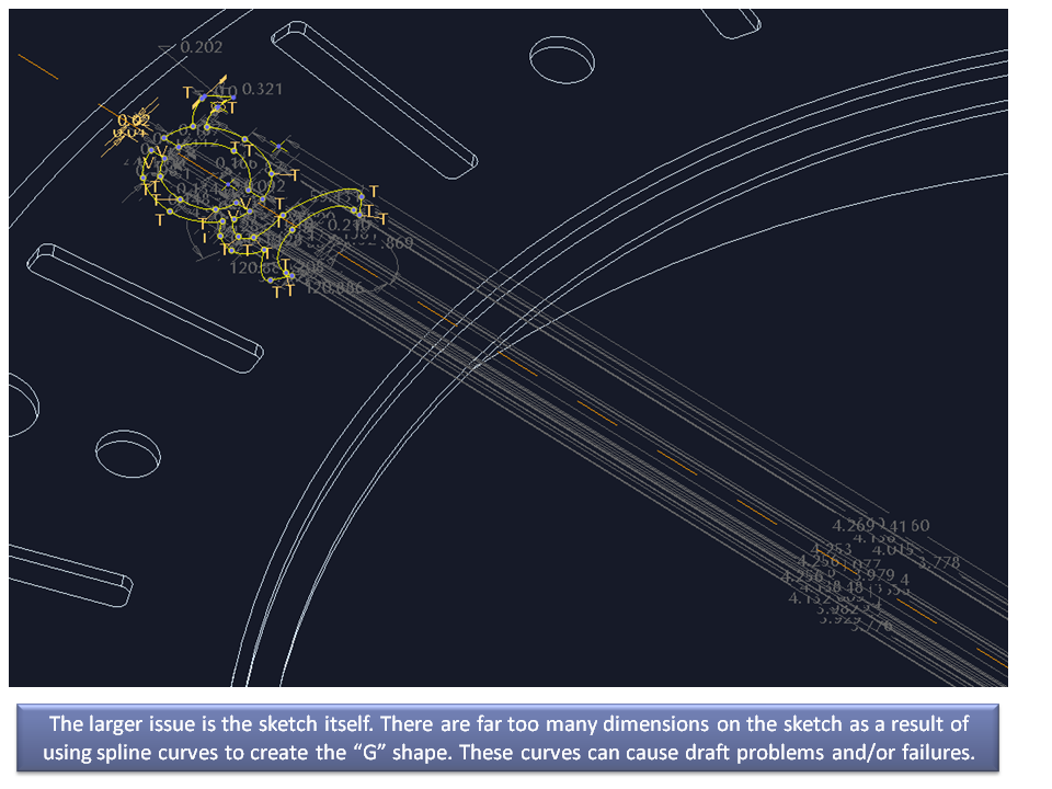
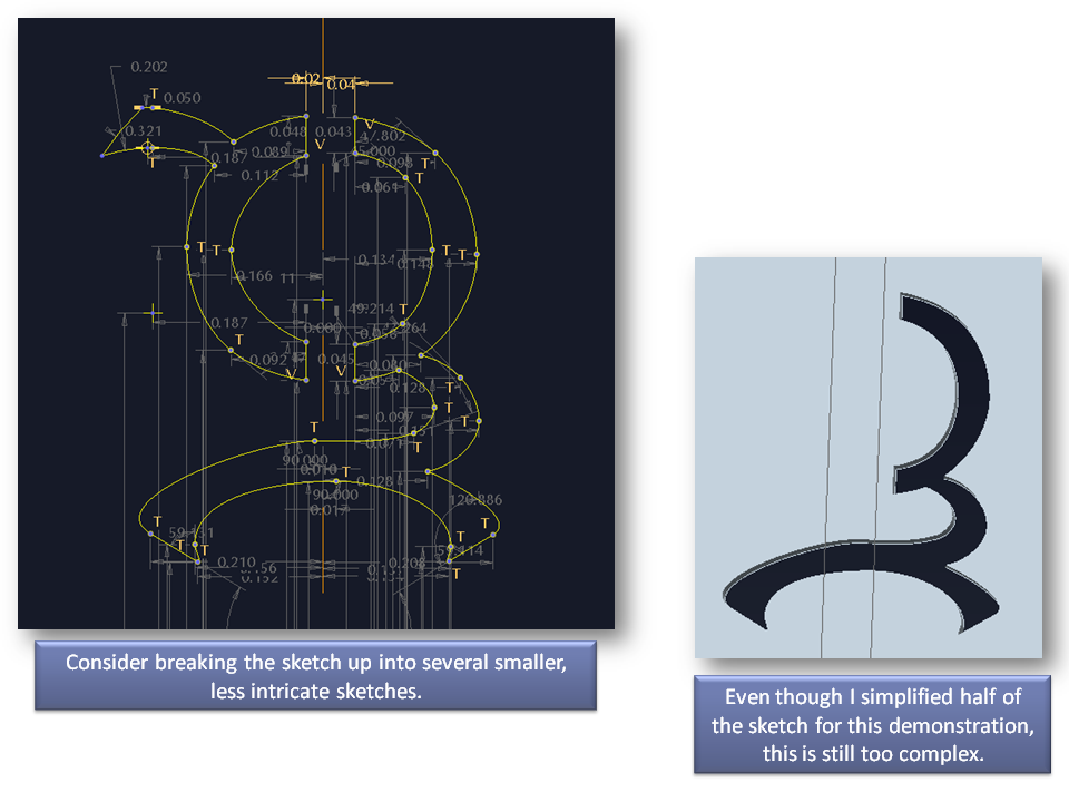
You're going to have a tough time with a logo-like sketch. It's always going to be messy with far too many controlling dimensions. My best advice would be to spend time simplifying the sketch. Try to generate the shape you want with as few dimensions and as little "crazy geometry" as possible. This will likely take some time but the payoff will be functional draft without the need for a sweep or surface geometry to create the piece you want.
Take a look at the slides below... click them for a larger, more readable image.
I hope this helped a little...
Thanks!
-Brian
3 REPLIES 3
Oct 03, 2012
10:52 AM
- Mark as New
- Bookmark
- Subscribe
- Mute
- Subscribe to RSS Feed
- Permalink
- Notify Moderator
Oct 03, 2012
10:52 AM
Hi Colette...
Depending upon your geometry, drafts can sometimes be tricky. Sure enough, in this case your geometry is causing the problem. Per the PTC Help Guide on drafts: You can draft only the surfaces that are formed by tabulated cylinders or planes. What this is saying (albeit cryptically) is that spline surfaces or complex curvatures may cause problems requiring alternate techniques to resolve.
I managed to draft the surfaces you were having problems with by using a Variable Section Sweep. First, I had to remove the micro-rounds in the corners (see slides below). I used the Complete Loop option of a Variable Section Sweep (VSS) to achieve this. I detailed the steps to accessing this option below.
Your geometry is the real culprit here, though. I realize you're trying to use a stylized piece of geometry- like a logo. These are often very "swooshy" and artistic looking with lots of curves and splines and conics. From experience I can tell you Creo can't always handle drafts on these surfaces due to the self-intersecting nature of those drafts. for example, in those tight "turns" (especially the ones circled in red below featuring the rounds), drafting becomes very tough.
You're going to have a tough time with a logo-like sketch. It's always going to be messy with far too many controlling dimensions. My best advice would be to spend time simplifying the sketch. Try to generate the shape you want with as few dimensions and as little "crazy geometry" as possible. This will likely take some time but the payoff will be functional draft without the need for a sweep or surface geometry to create the piece you want.
Take a look at the slides below... click them for a larger, more readable image.
I hope this helped a little...
Thanks!
-Brian
Oct 03, 2012
01:58 PM
- Mark as New
- Bookmark
- Subscribe
- Mute
- Subscribe to RSS Feed
- Permalink
- Notify Moderator
Oct 03, 2012
01:58 PM
I've had similar probkems as Brian describes with complex logo's. There were times I had to import the entire logo (from autoCAD), and let sketcher create a zillion dimensions simply because there was no way to accurately do it one letter/figure at a time. I WISH there was an option to import geometry as a "block" like an AutoCAD block where you only get the option of scaling and/or rotating the whole thing. THAT is a much needed feature. But, what I find helps, is go into the sketcher options and turn off all the automatic constraints BEFORE you import the sketch. this prevents the sketcher from assuming almost everything, and just creates the mentioned zillion dims. Then set the selection filter to "dimensions", highlight everything, and lock them. Then, if there are any constraints, set the filter for that and make them strong. It's not perfect, but it definately helps.
As he mentioned, the more complicated the geometry, the more trouble you'll have adding draft to it. And, also, in 99% of cases, rounds should always be added AFTER draft anyways, because of tooling issues (ball-end milling cutters, etc.).
Good luck.
Oct 03, 2012
03:03 PM
- Mark as New
- Bookmark
- Subscribe
- Mute
- Subscribe to RSS Feed
- Permalink
- Notify Moderator
Oct 03, 2012
03:03 PM
Hi,
I think you should be able to copy the border curve of your letter and make an offset curve of off it in such distance that it is related to your angle. Using relation and maybe some measurement analysis.
Then simply (ok not simply) make a boundary blend of off that curve and the loop of your letter and use solidify to remove the material. In case this draft removes the material. In case the draft adds material you will need to use additional fill feature and merge this one with the blend.
I guess as long as you avoid using sketcher you could actually follow the shape even if it's made from all splines but from my experience some edit features in Creo don't work while using splines.
So maybe with all that you would need to use extend feature too and maybe it would result in a total mess but that's another way to go other than using Sweep feature.
EDIT: I've just tried Brian's method and the sweeps created the draft cuts with no problem. All I needed to do was to set the model accuracy to absolute 0.0005.
