
Turn on suggestions
Auto-suggest helps you quickly narrow down your search results by suggesting possible matches as you type.
Showing results for
Turn on suggestions
Auto-suggest helps you quickly narrow down your search results by suggesting possible matches as you type.
Showing results for
Community Tip - You can change your system assigned username to something more personal in your community settings. X
- Community
- Creo+ and Creo Parametric
- 3D Part & Assembly Design
- Helical sweep with variable pitch vanes
Options
- Subscribe to RSS Feed
- Mark Topic as New
- Mark Topic as Read
- Float this Topic for Current User
- Bookmark
- Subscribe
- Mute
- Printer Friendly Page
Helical sweep with variable pitch vanes
Jan 13, 2014
04:24 PM
- Mark as New
- Bookmark
- Subscribe
- Mute
- Subscribe to RSS Feed
- Permalink
- Notify Moderator
Jan 13, 2014
04:24 PM
Helical sweep with variable pitch vanes
Here's my issue, I am designing a part with a helical sweep where the pitch varies from 1.33 to 4.6. This part is no problem, the issue is we want to be able to mold this part and as you can see in the picture the vanes wrap around on themselfs. I think if I could keep the vane perpendicular to the asis it could be moldable. I've tried this using both helical sweep and swept blend to no avail. Thanks in advance.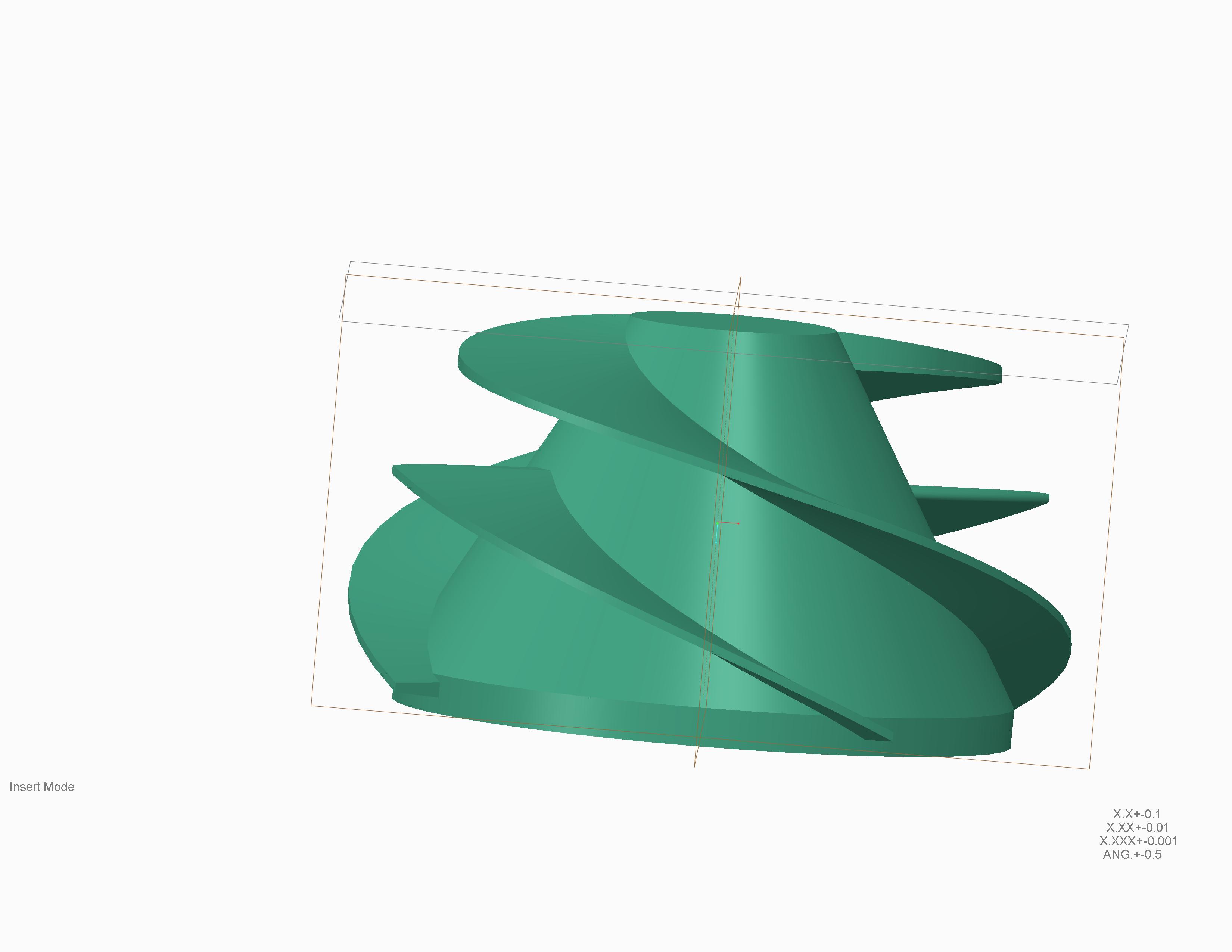
This thread is inactive and closed by the PTC Community Management Team. If you would like to provide a reply and re-open this thread, please notify the moderator and reference the thread. You may also use "Start a topic" button to ask a new question. Please be sure to include what version of the PTC product you are using so another community member knowledgeable about your version may be able to assist.
Labels:
- Labels:
-
General
10 REPLIES 10
Jan 13, 2014
05:27 PM
- Mark as New
- Bookmark
- Subscribe
- Mute
- Subscribe to RSS Feed
- Permalink
- Notify Moderator
Jan 13, 2014
05:27 PM
You will not be able to mold that as a typical 2-sided mold. With a helix thare's always the issue of negative draft/undercuts. You will need a spinning core, and even then, because of the change in pitch, it might not work. Depending on how soft the material is, you MIGHT be able to, with a ton of radial slides, pop th epart out with proper sequencing, but it goes back to the elasticity of the plastic.
Best of luck.
Jan 13, 2014
07:35 PM
- Mark as New
- Bookmark
- Subscribe
- Mute
- Subscribe to RSS Feed
- Permalink
- Notify Moderator
Jan 13, 2014
07:35 PM
Frank is right, this type of part is made with investment casting.
Typically a lost wax master with a hard shell for the casting process.
If the material is a castable plastic, you might be able to get away with a flexible silicon mold where you could peel the mold away from the part.
Jan 13, 2014
07:45 PM
- Mark as New
- Bookmark
- Subscribe
- Mute
- Subscribe to RSS Feed
- Permalink
- Notify Moderator
Jan 13, 2014
07:45 PM
'Sup Antonius! Yeah, I assumed he meant in plastic. That's gonna be pretty impossible to "mold". A spinning core MIGHT work, if the pitch change was in the other direction. Have to give it more thought......
I'll try and look at that stuff tomorrow!
Jan 13, 2014
09:30 PM
- Mark as New
- Bookmark
- Subscribe
- Mute
- Subscribe to RSS Feed
- Permalink
- Notify Moderator
Jan 13, 2014
09:30 PM
That looks like a washing machine agitator? If molding is a requirement and you can vary the design, then you will probably have to do a lot of tweaking, like maybe being thicker towards the center but then having the profile change a bit at places where there will be parting lines.
Jan 14, 2014
09:44 AM
- Mark as New
- Bookmark
- Subscribe
- Mute
- Subscribe to RSS Feed
- Permalink
- Notify Moderator
Jan 14, 2014
09:44 AM
Thanks for the feed back.
The part is an impeller for a water pump and the intent of the project was to injection mold it. I couldn't come up with a way to do it and hoped you guys could but you did confirm that I was right.
thanks for your help.
Jan 14, 2014
12:19 PM
- Mark as New
- Bookmark
- Subscribe
- Mute
- Subscribe to RSS Feed
- Permalink
- Notify Moderator
Jan 14, 2014
12:19 PM
Like I said, a spinning core MIGHT do it if the pitch was static, and the vanes were constant or decreasing in section. Conventional molding? Not a chance. It's just the geometry.
Jan 14, 2014
03:14 PM
- Mark as New
- Bookmark
- Subscribe
- Mute
- Subscribe to RSS Feed
- Permalink
- Notify Moderator
Jan 14, 2014
03:14 PM
The conical shape along the OD helps... but in order to spin the part out of the tool, the thickness of the vanes would have to vary to make up for the pitch change. The conical shape helps limit the total pitch variation to only that which is engaged. However, this practice is a huge hit to performance and even the pitch variable would have to be recalculated for optimal performance. You might also be able to take on a minor advantage if the material is flexible enough. You will also have to be very careful about the torque required to spin the part out of the tool. Splitting the tool will help.
Jan 14, 2014
04:47 PM
- Mark as New
- Bookmark
- Subscribe
- Mute
- Subscribe to RSS Feed
- Permalink
- Notify Moderator
Jan 14, 2014
04:47 PM
Yeah, there's a whole host of things you'd have to do. The variable pitch itself would probably be a show-stopper in itself, unless you made the vanes very thick at one end so that the tool would clear as it spun. If it was a static pitch, as long as you had HELICAL draft on the vanes, it'd work. I did something similar with a static pitch for a 6-lobed core (I believe it's in my photo album).
Flexibility of the part would help only slightly I think, you'd still have to worry about the tool shearing off the vane where it joins the cone, regardless of the outer edges bending.
Tough part to mold!
Question to the OP: Could the vanes be modified to make it moldable, of is that configuration absolutely needed for performance?
Jan 14, 2014
04:56 PM
- Mark as New
- Bookmark
- Subscribe
- Mute
- Subscribe to RSS Feed
- Permalink
- Notify Moderator
Jan 14, 2014
04:56 PM
The vane thickness could be modified slightly but the way it looks is pretty critical to the preformance. I have investigated creating a helical sweep on the base diameter then using that sweep to project to keeping the vanes straight. That didn't work out. What I am looking at now is seeing if I can mold this in 3? parts then assemble it back into an assembly. We currently make some colsed impeller in two parts and sonic weld them back together, this works pretty well. With this I'm not sure yet, I know I'll have to work close with the molder.
thanks
Jan 14, 2014
04:58 PM
- Mark as New
- Bookmark
- Subscribe
- Mute
- Subscribe to RSS Feed
- Permalink
- Notify Moderator
Jan 14, 2014
04:58 PM
I'll bet what you'll need then is a bunch of carefully-sequenced, radial slides.
Best of luck!
