
Turn on suggestions
Auto-suggest helps you quickly narrow down your search results by suggesting possible matches as you type.
Showing results for
Turn on suggestions
Auto-suggest helps you quickly narrow down your search results by suggesting possible matches as you type.
Showing results for
Community Tip - Did you get called away in the middle of writing a post? Don't worry you can find your unfinished post later in the Drafts section of your profile page. X
- Community
- Creo+ and Creo Parametric
- 3D Part & Assembly Design
- Help modeling boat hull in sheetmetal
Options
- Subscribe to RSS Feed
- Mark Topic as New
- Mark Topic as Read
- Float this Topic for Current User
- Bookmark
- Subscribe
- Mute
- Printer Friendly Page
Help modeling boat hull in sheetmetal
Aug 26, 2014
01:02 PM
- Mark as New
- Bookmark
- Subscribe
- Mute
- Subscribe to RSS Feed
- Permalink
- Notify Moderator
Aug 26, 2014
01:02 PM
Help modeling boat hull in sheetmetal
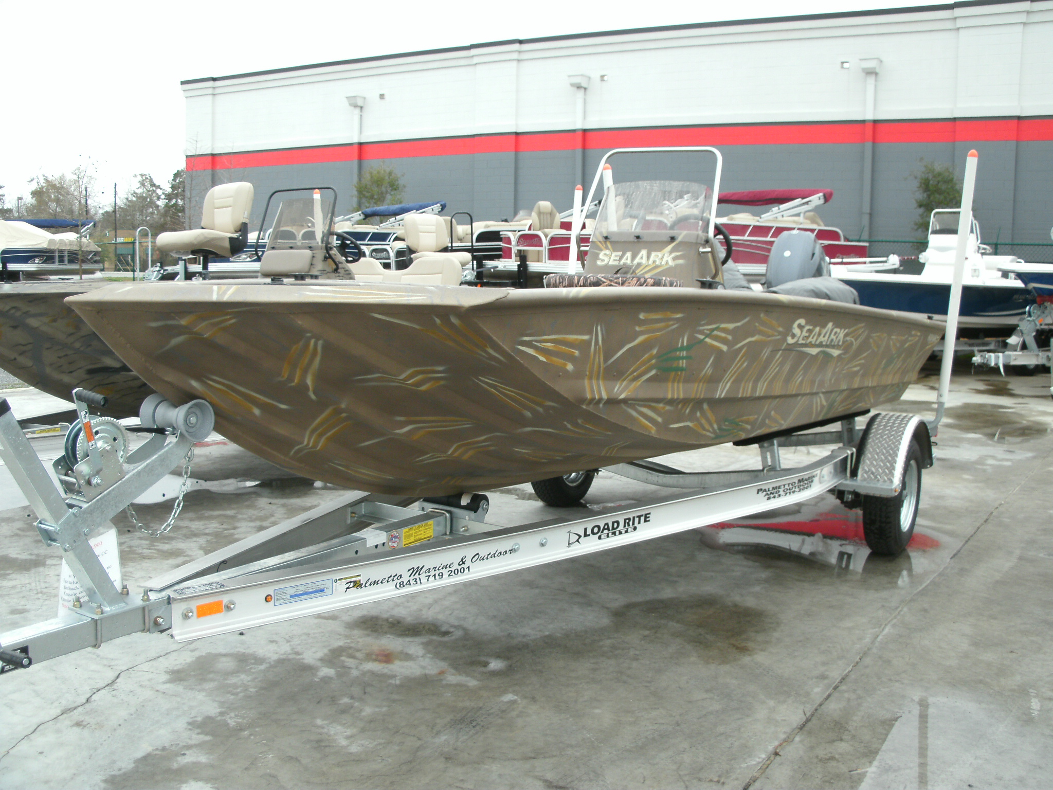
Hello I am rather new to working with the sheetmetal feature in creo/pro e and was looking for some help in modeling a boat hull. I am trying to bend the shape below to match the photo attached any help with how to accomplish this would be very much appreciated. The two curved lines should meet and transition into the flat part of the hull bottom.
This thread is inactive and closed by the PTC Community Management Team. If you would like to provide a reply and re-open this thread, please notify the moderator and reference the thread. You may also use "Start a topic" button to ask a new question. Please be sure to include what version of the PTC product you are using so another community member knowledgeable about your version may be able to assist.
Labels:
- Labels:
-
General
16 REPLIES 16
Aug 26, 2014
01:26 PM
- Mark as New
- Bookmark
- Subscribe
- Mute
- Subscribe to RSS Feed
- Permalink
- Notify Moderator
Aug 26, 2014
01:26 PM
Joshua,
Others might have some other methods, but I think this application might lend itself to modeling the final desired shape as a solid all formed up and then doing a Sheetmetal Conversion to get the flat state of the model. In the Sheetmetal conversion, you can define the ripping places to get your flat shape.
Aug 26, 2014
02:37 PM
- Mark as New
- Bookmark
- Subscribe
- Mute
- Subscribe to RSS Feed
- Permalink
- Notify Moderator
Aug 26, 2014
02:37 PM
I too would work with a solid model if all you want is the boat hull and not try fabricating it.
Boundary Blend will make the bottom and some strategic sweeps will make the ribs. Build the side and back wall, then close it up with another boundary blend. If you are lucky, you can then shell the hull. Finish with some additional sweeps and rounds.
If you have good orthographic images of boat, you can use these as underlays for guides.
Aug 26, 2014
02:44 PM
- Mark as New
- Bookmark
- Subscribe
- Mute
- Subscribe to RSS Feed
- Permalink
- Notify Moderator
Aug 26, 2014
02:44 PM
Here's a start ... 
Aug 26, 2014
02:51 PM
- Mark as New
- Bookmark
- Subscribe
- Mute
- Subscribe to RSS Feed
- Permalink
- Notify Moderator
Aug 26, 2014
02:51 PM
I intend to actually manufacturer this boat and use these models for cnc programming so i will have to convert them to sheet metal at some point. I think i will try to plot out my cross sections and do a blend.
Aug 26, 2014
03:27 PM
- Mark as New
- Bookmark
- Subscribe
- Mute
- Subscribe to RSS Feed
- Permalink
- Notify Moderator
Aug 26, 2014
03:27 PM
Because you are working with such large panels and very little deformation, you can use flattened quilts to come up with very close results.
Are you planning on merging the sides and back to a single piece and welding the seams?
There is a lot to consider when designing such a hull. You might even think of stopping by the local hobby shop and picking up some brass sheets. You can print on these and cut out your patterns and solder them together. This will give you an idea of what kind of deformation you are dealing with.
Aug 26, 2014
03:37 PM
- Mark as New
- Bookmark
- Subscribe
- Mute
- Subscribe to RSS Feed
- Permalink
- Notify Moderator
Aug 26, 2014
03:37 PM
yes we build the majority of our larger boats in 4 pieces (2 sides, bottom, and the back). all seams are welded and they have crimped ribs performed on a large metal brake. How does the flattend quilts feature work?
Aug 26, 2014
03:47 PM
- Mark as New
- Bookmark
- Subscribe
- Mute
- Subscribe to RSS Feed
- Permalink
- Notify Moderator
Aug 26, 2014
03:47 PM
There are a lot of options but typically, if you create a datum point along a straight edge, it works without trouble. It uses the plane of that edge at the point's location to determine the projection (unfurl) plane.
It takes a little getting use to and it does make assumptions.
There is also a flatten quilt dedformation to keep in mind. If you need to add planar references, you can add them in 3D using this command.
For your work, this is worth getting some practice time in.
Lots of discussions on the web and here. A good sample... how to develop this?
If you cannot get it to work, just add a rough part file here (full version please!) and we can take a look. You can attach files in the advanced editor.
Aug 26, 2014
03:49 PM
- Mark as New
- Bookmark
- Subscribe
- Mute
- Subscribe to RSS Feed
- Permalink
- Notify Moderator
Aug 26, 2014
03:49 PM
thanks for the help looks like i have my afternoon planned out now.
Aug 26, 2014
05:20 PM
- Mark as New
- Bookmark
- Subscribe
- Mute
- Subscribe to RSS Feed
- Permalink
- Notify Moderator
Aug 26, 2014
05:20 PM
Do I have a future in boat building  ???
???
This should give you some tips. Creo 2.0 full version attached.
Aug 27, 2014
12:12 PM
- Mark as New
- Bookmark
- Subscribe
- Mute
- Subscribe to RSS Feed
- Permalink
- Notify Moderator
Aug 27, 2014
12:12 PM
Antonius,
Yes you can create a true sheetmetal part from a solid using the Conversion. Please see this link:
http://learningexchange.ptc.com/tutorial/410/using-the-conversion-tool
This is what I was talking about with creating the shelled solid and then ripping it where needed.
Aug 27, 2014
01:19 PM
- Mark as New
- Bookmark
- Subscribe
- Mute
- Subscribe to RSS Feed
- Permalink
- Notify Moderator
Aug 27, 2014
01:19 PM
I did try making the hull I made in sheetmetal. I got it to rip fine, but it did not recognize the bends even though I was very careful about keeping the flat surfaces flat. In general, many of these surfaces in practice are "twisted" and that simple won't work in sheetmetal unless you make the twist in sheetmetal.
I am certainly not suggesting it isn't possible, but for the most part, it is not necessary.
Aug 27, 2014
09:35 AM
- Mark as New
- Bookmark
- Subscribe
- Mute
- Subscribe to RSS Feed
- Permalink
- Notify Moderator
Aug 27, 2014
09:35 AM
Thank you for your help Antonius i walked through your model and made an attempt to take the same approach but i cannot get the sweeps to work correctly is this due to poor datum selection? I have attached the file if you like to take a look .
Aug 27, 2014
01:32 PM
- Mark as New
- Bookmark
- Subscribe
- Mute
- Subscribe to RSS Feed
- Permalink
- Notify Moderator
Aug 27, 2014
01:32 PM
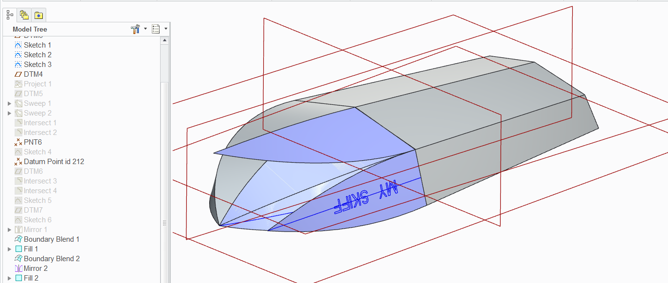
Joshua, sweeps here are a little particular. You have a twist in the side and this means you need a variable section sweep (VSS). That is the last button in the dialog. You also cannot sweep a projected feature. You have to make the line that changes angle through the sweep (not locked to vertical or fixed angle). This means you need not only the origin, but you need a "chain"... a guide curve. Another problem with sweep is the ends can be cut short since they do not extend by default. I extended some to get an intersect for next level geometry.
Having said all that, a boundary blend gets rid of some of this frustration and begins a few others.
In general, I would suggest creating all the "edges" of the boat, somewhat wireframe if you will, to use as reference geometry.
I made master sections; only 3 in my case but more is better; I created edges from swept surfaces with intersects; I created points at strategic corners; and I created sketch planes thought points to get more edges.
Now this takes a lot of the creativity out of the process. But this is not a fiberglass boat so you need some level of workability for the raw panels.
I would say you still need to work out the remaining edges. Boundary blends will manage most of the remainder. Doing the flatten quilts can get tricky but it should get you what you want eventually. It just requires patience.
Aug 27, 2014
01:56 PM
- Mark as New
- Bookmark
- Subscribe
- Mute
- Subscribe to RSS Feed
- Permalink
- Notify Moderator
Aug 27, 2014
01:56 PM
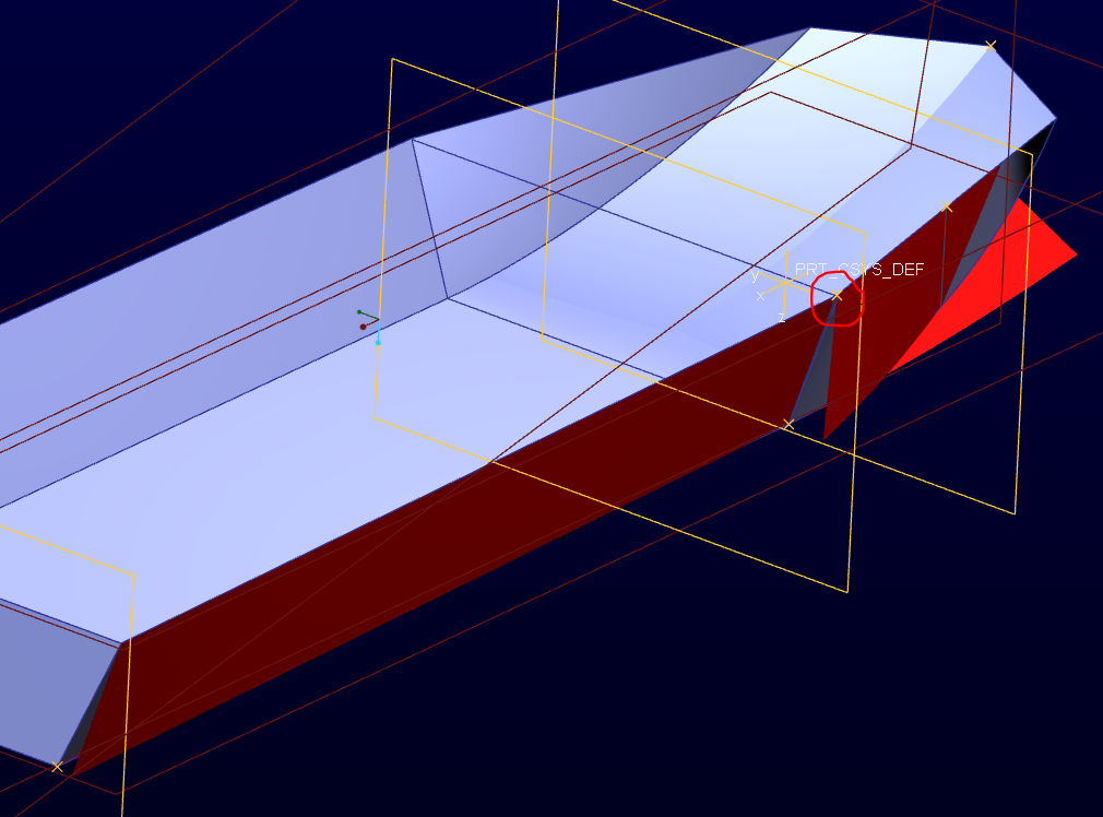
Here is a quick sheeting of the hull. The red circle shows an area where you are not meeting the two orthographic sketches.
The flatten quilt untwists the side just fine. The side triangle worked easily enough, and so did the bottom that is bent to the nose.
Use sketch references to make sure corners remain coincident from one sketch to the next. If you cannot use references, use relations. If you cannot use relations, use surface intersections to create geometry.
Aug 27, 2014
01:58 PM
- Mark as New
- Bookmark
- Subscribe
- Mute
- Subscribe to RSS Feed
- Permalink
- Notify Moderator
Aug 27, 2014
01:58 PM
And another mismatch here:

Aug 27, 2014
02:00 PM
- Mark as New
- Bookmark
- Subscribe
- Mute
- Subscribe to RSS Feed
- Permalink
- Notify Moderator
Aug 27, 2014
02:00 PM
thanks i will work on trying to fix those issues this evening.
