
Turn on suggestions
Auto-suggest helps you quickly narrow down your search results by suggesting possible matches as you type.
Showing results for
Turn on suggestions
Auto-suggest helps you quickly narrow down your search results by suggesting possible matches as you type.
Showing results for
Community Tip - Did you get called away in the middle of writing a post? Don't worry you can find your unfinished post later in the Drafts section of your profile page. X
- Community
- Creo+ and Creo Parametric
- 3D Part & Assembly Design
- How to Flatten Quilt a Semi-Spherical Surface
Options
- Subscribe to RSS Feed
- Mark Topic as New
- Mark Topic as Read
- Float this Topic for Current User
- Bookmark
- Subscribe
- Mute
- Printer Friendly Page
How to Flatten Quilt a Semi-Spherical Surface
Apr 17, 2014
10:50 AM
- Mark as New
- Bookmark
- Subscribe
- Mute
- Subscribe to RSS Feed
- Permalink
- Notify Moderator
Apr 17, 2014
10:50 AM
How to Flatten Quilt a Semi-Spherical Surface
Hi there Guys,
I'm a industrial designer and new Creo Parametric 2.0 user. In fact, i'm testing CREO to implement it in the company I work for.
We are a Pressure Vessel Designer and Manufacturer so, most of our pruducts will need the feature I'm looking for.
I'm trying to flatten quilt a semi-spherical surface so I can define the size of the plate to be used in the manufacture of a Vessel Head. Obviously, The area of a Sphere suface is a known area, but I'm just using it as an exemple. Vessel head will have Semieliptical, torispherical, and some other forms with more than one radius and etc. Also I don't know if i'm using the correct feature. I was able to flatten and curved surface, but not a domed one. Can anyone help me?
This thread is inactive and closed by the PTC Community Management Team. If you would like to provide a reply and re-open this thread, please notify the moderator and reference the thread. You may also use "Start a topic" button to ask a new question. Please be sure to include what version of the PTC product you are using so another community member knowledgeable about your version may be able to assist.
7 REPLIES 7
Apr 17, 2014
12:11 PM
- Mark as New
- Bookmark
- Subscribe
- Mute
- Subscribe to RSS Feed
- Permalink
- Notify Moderator
Apr 17, 2014
12:11 PM
In the real world you cannot flatten a domed part without significantly stretching the material (at the circumference), it is a non-developable surface. Likewise you cannot create a domed part from a flat piece of sheetmetal without stamping/deep-drawing it.
So, the end result is going to be a little funny if you try and flatten it. There was some work done here by sever people, Antonius the most prominent, dealing with doming a mesh, I'd search that thread.
Apr 17, 2014
04:30 PM
- Mark as New
- Bookmark
- Subscribe
- Mute
- Subscribe to RSS Feed
- Permalink
- Notify Moderator
Apr 17, 2014
04:30 PM
Yes Frank. I understand the problem with the material deformation, but CAD softwares works with geometries in a first place, so, why it can't give me a geometrical solution? Otherwise, what solution could I take? Should I create tools for stamping flat pieces in sheetmetal?
Apr 17, 2014
04:58 PM
- Mark as New
- Bookmark
- Subscribe
- Mute
- Subscribe to RSS Feed
- Permalink
- Notify Moderator
Apr 17, 2014
04:58 PM
The reason there isn't a flat pattern solution is that there is not a on-to-one correspondance in distances between points on the neutral plane in the formed part and any possible flat pattern.
The reason for this is that the material thickness changes, not it's bent shape, and the thickness change is the result of a complex combination of deformations that is infrequently investigated using FEA tools because it's an elastic-to-plastic transition.
In typical forming operations, the flat pattern is just the same as the projected shape of the formed part, but with thicker material and some margin to hold onto or trim off.
PTC simulates this with sheet-metal form tools that simply replace the existing geometry with the as-formed geometry, but without consideration for the material thinning to the flat part to generate the formed version.
A similar situation applies to vacuum-formed items; there's no sensible flat pattern except a piece of material that is large enough to cover the mold and thick enough not to rupture when formed.
Apr 17, 2014
05:23 PM
- Mark as New
- Bookmark
- Subscribe
- Mute
- Subscribe to RSS Feed
- Permalink
- Notify Moderator
Apr 17, 2014
05:23 PM
Excellent explanation David! 
Apr 17, 2014
06:24 PM
- Mark as New
- Bookmark
- Subscribe
- Mute
- Subscribe to RSS Feed
- Permalink
- Notify Moderator
Apr 17, 2014
06:24 PM
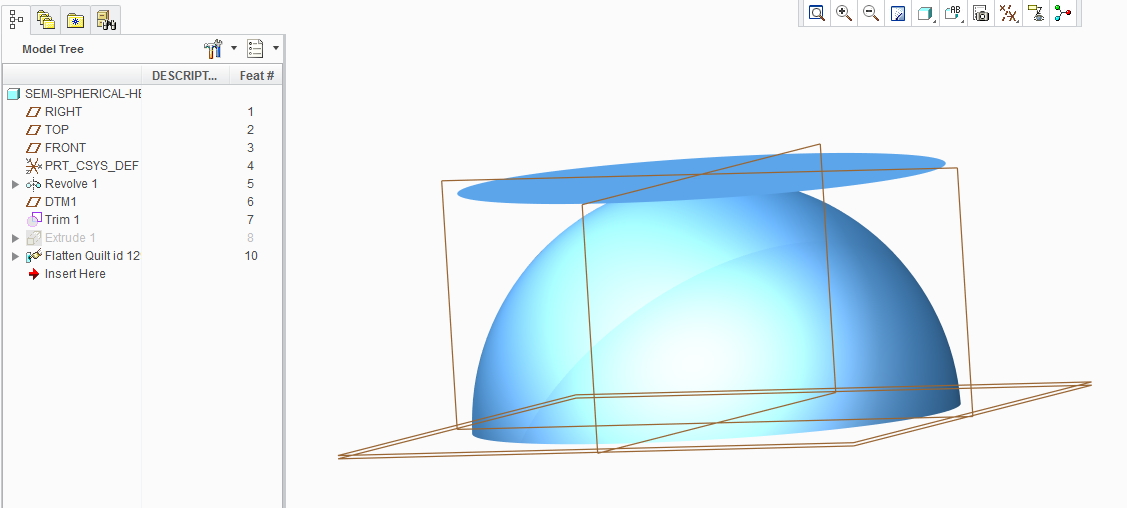
Placing the physics of the material aside, you can perform a "flatten-quilt" on domed geometry as opposed to a sheet metal "flat patten", if that's what you are trying to do. That being said, you cannot perform a flatten-quilt with your particular geometry due to the fact that the sides of the dome become normal to the flattening plane. If you trimmed it just past that point, it will work, see below. You could also cut the model in quarters and flatten to a plane that is at 45deg. You'll also need to do a manual parametrization because of the compound curvature. Given the limitations of this feature, you ultimately may not be able to create what you are intending to if you really need the vertical walls.
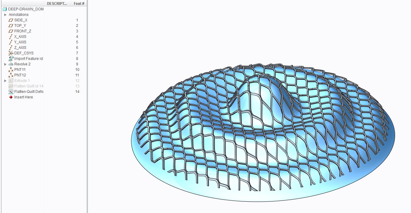
Just be aware that at this point you've crossed the boundries of reality and wandered into cartoon land. And, as David stated, the flatten-quilt is just a projection. So if you are fine with those aspects of it, you can create the flatten-quilt but it's real benefit comes from using it as a form to "cartoon" bend solid shapes, curves, etc. that may not be possible to model any other way.
The picture below is from the discussion (Solid "Deep Drawing" (how to?)) Frank mentioned. As you can see, reality has been breached. But it has its uses.
Apr 18, 2014
09:32 AM
- Mark as New
- Bookmark
- Subscribe
- Mute
- Subscribe to RSS Feed
- Permalink
- Notify Moderator
Apr 18, 2014
09:32 AM
....reality is overrated.....
Apr 18, 2014
02:26 AM
- Mark as New
- Bookmark
- Subscribe
- Mute
- Subscribe to RSS Feed
- Permalink
- Notify Moderator
Apr 18, 2014
02:26 AM
I have an solution its may not be so correct but we use it for this kinda head.
Step 1: Measure the area of the head and save as feature.
Step 2: enter the formula in relation, dia= sqrt(area(of the saved measure feature)*4/pi())
Step 2: Draw an surface or extrusion with that diamter.
This is a manual solution, may be work for you. You may add sufficent allowance (from some standards or experience) with the measured area for getting the actual diameter. However since its a drawing operation, unbend may not be possible.
Regards,
Jayanta Sarkar
