
Turn on suggestions
Auto-suggest helps you quickly narrow down your search results by suggesting possible matches as you type.
Showing results for
Turn on suggestions
Auto-suggest helps you quickly narrow down your search results by suggesting possible matches as you type.
Showing results for
Community Tip - Your Friends List is a way to easily have access to the community members that you interact with the most! X
- Community
- Creo+ and Creo Parametric
- 3D Part & Assembly Design
- How to Use Sweep Blend with what I'm trying to do?
Options
- Subscribe to RSS Feed
- Mark Topic as New
- Mark Topic as Read
- Float this Topic for Current User
- Bookmark
- Subscribe
- Mute
- Printer Friendly Page
How to Use Sweep Blend with what I'm trying to do?
May 10, 2016
04:42 PM
- Mark as New
- Bookmark
- Subscribe
- Mute
- Subscribe to RSS Feed
- Permalink
- Notify Moderator
May 10, 2016
04:42 PM
How to Use Sweep Blend with what I'm trying to do?
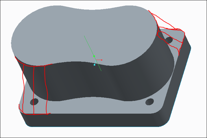
I've been trying to find a way to get the top rectangular edge to blend with the edge of the peanut shape,such that it appears trapezoidal. I'm creating a straight line that vertically intersects the middle of the peanut shape's top plane and the center of the rectangle's top plane. Then I use the project feature in the sketcher to to retrace the rectangle for the first sketch, then for the second sketch i do the same for the peanut shape. However, it won't generate the sweep and I can't figure out how.
Anyone?
This thread is inactive and closed by the PTC Community Management Team. If you would like to provide a reply and re-open this thread, please notify the moderator and reference the thread. You may also use "Start a topic" button to ask a new question. Please be sure to include what version of the PTC product you are using so another community member knowledgeable about your version may be able to assist.
Solved! Go to Solution.
Labels:
- Labels:
-
General
1 ACCEPTED SOLUTION
Accepted Solutions
May 11, 2016
07:13 AM
- Mark as New
- Bookmark
- Subscribe
- Mute
- Subscribe to RSS Feed
- Permalink
- Notify Moderator
14 REPLIES 14
May 11, 2016
07:13 AM
- Mark as New
- Bookmark
- Subscribe
- Mute
- Subscribe to RSS Feed
- Permalink
- Notify Moderator
May 11, 2016
07:13 AM
Casey,
Is this what you are expecting?

May 11, 2016
09:43 AM
- Mark as New
- Bookmark
- Subscribe
- Mute
- Subscribe to RSS Feed
- Permalink
- Notify Moderator
May 11, 2016
09:43 AM
Yes, that's it! How did you do??
May 11, 2016
10:50 AM
- Mark as New
- Bookmark
- Subscribe
- Mute
- Subscribe to RSS Feed
- Permalink
- Notify Moderator
May 11, 2016
10:50 AM
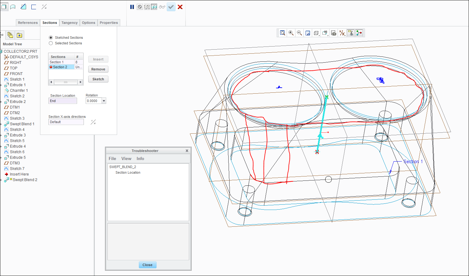
I used swept blend- used your centre curve as main trajectory and the sketched 2 sections using your curves. In the second sketch you need to divide the curve to used as blend vertex.
I will send you the model soon.
May 11, 2016
11:25 AM
- Mark as New
- Bookmark
- Subscribe
- Mute
- Subscribe to RSS Feed
- Permalink
- Notify Moderator
May 11, 2016
11:25 AM
It would be interesting know how to get it to work. Maybe I'm just too inexperienced, but I'm having a hard time. I have been trying to do it using the sketch feature, but can't get it to generate. I also can't seem to figure out how to get the selected curve method of swept blend to work either. I don't seem to understand what the blend vertex is.
Thanks!
May 11, 2016
11:24 AM
- Mark as New
- Bookmark
- Subscribe
- Mute
- Subscribe to RSS Feed
- Permalink
- Notify Moderator
May 11, 2016
12:59 PM
- Mark as New
- Bookmark
- Subscribe
- Mute
- Subscribe to RSS Feed
- Permalink
- Notify Moderator
May 11, 2016
12:59 PM
Thank you very much. The problem I'm having is after I make the second sketch I'm not sure what to do. What would be the next step? I'm trying to remove material from the red trace and a sketch that is on the top, which removed the material along the line i made in this file.
May 11, 2016
10:16 AM
- Mark as New
- Bookmark
- Subscribe
- Mute
- Subscribe to RSS Feed
- Permalink
- Notify Moderator
May 11, 2016
10:16 AM
Hi, you could try an old school feature called Blend Section to Surface. You will have to search for it, as it is not readily available in the standard Creo toolbars. See the attached model, it might yield satisfactory results.
John
May 11, 2016
11:11 AM
- Mark as New
- Bookmark
- Subscribe
- Mute
- Subscribe to RSS Feed
- Permalink
- Notify Moderator
May 11, 2016
11:11 AM
I can't seem to find that feature for Creo 2.0. I tried the blend to tangents and can't get that to work either. Also, your file doesn't seem to open.
May 12, 2016
10:44 AM
- Mark as New
- Bookmark
- Subscribe
- Mute
- Subscribe to RSS Feed
- Permalink
- Notify Moderator
May 12, 2016
10:44 AM
I attach a similar model in Creo 2 so you can see the feature I describe.
John
May 11, 2016
03:22 PM
- Mark as New
- Bookmark
- Subscribe
- Mute
- Subscribe to RSS Feed
- Permalink
- Notify Moderator
May 11, 2016
03:22 PM
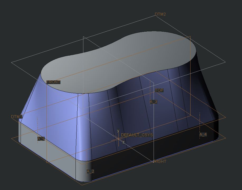
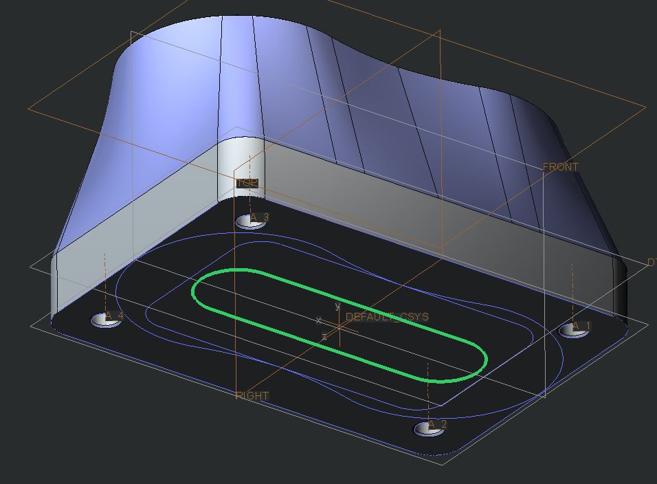
Here's another solution using a Variable Section Sweep. I created another trajectory (on the bottom) to control the section normal. It's a simple oval. The section is a straight line between the two edges.
It produces a slightly different shape:
May 12, 2016
10:16 AM
- Mark as New
- Bookmark
- Subscribe
- Mute
- Subscribe to RSS Feed
- Permalink
- Notify Moderator
May 12, 2016
10:16 AM
That looks great, too. Would you be able to share how you did in more detail?
May 12, 2016
11:53 AM
- Mark as New
- Bookmark
- Subscribe
- Mute
- Subscribe to RSS Feed
- Permalink
- Notify Moderator
May 12, 2016
11:53 AM
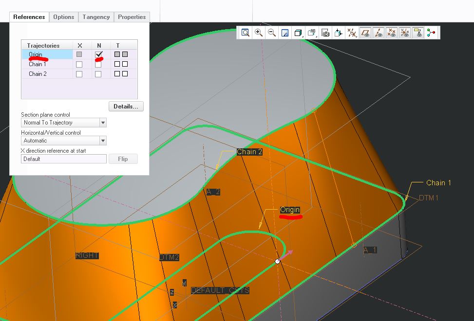
It's easiest for you to understand if you look at the model, but I'll give it a shot.
For a sweep, Creo needs to know how to position and orient the sketch as it travels along the trajectories. You need to define the sketch plane normal and the rotation along the trajectory.
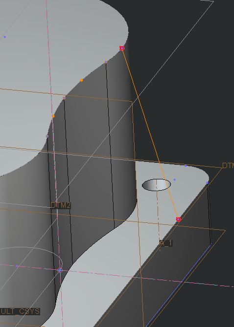
For the geometry you have, using either of the two trajectories as the normal trajectory (sketch plane stays normal to it all along the sweep) creates problems with overlapping geometry, By creating a third trajectory (a simple oval with the centers aligned with the centers of the peanut shape, see below) that only defines the normal of the sweep, I eliminated the overlapping geometry.
The section is then a straight line between the rectangular trajectory and the peanut trajectory.
May 13, 2016
12:13 AM
- Mark as New
- Bookmark
- Subscribe
- Mute
- Subscribe to RSS Feed
- Permalink
- Notify Moderator
May 13, 2016
12:13 AM
Hi Casey,
Another way is to use Boundary Blend surfaces.
e.g.
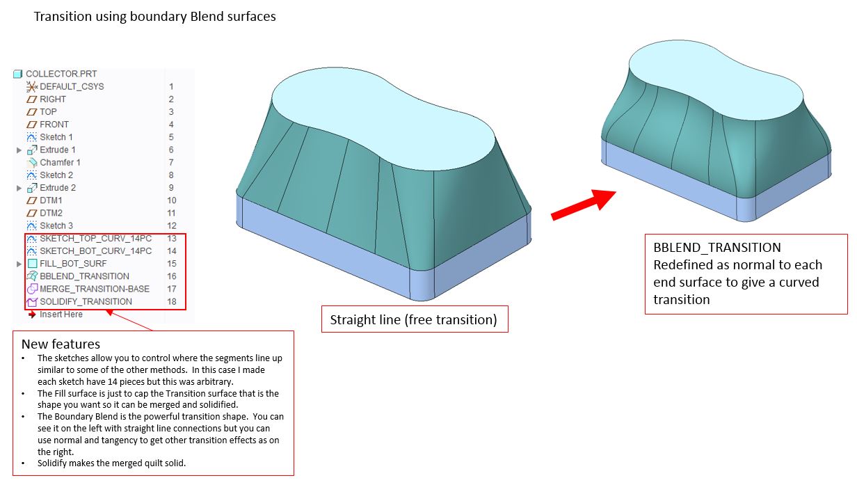
This allows a lot of control at the expense of a small amount of complexity.
Regards. Brent Drysdale
May 13, 2016
03:58 AM
- Mark as New
- Bookmark
- Subscribe
- Mute
- Subscribe to RSS Feed
- Permalink
- Notify Moderator
