
Turn on suggestions
Auto-suggest helps you quickly narrow down your search results by suggesting possible matches as you type.
Showing results for
Turn on suggestions
Auto-suggest helps you quickly narrow down your search results by suggesting possible matches as you type.
Showing results for
Community Tip - Your Friends List is a way to easily have access to the community members that you interact with the most! X
- Community
- Creo+ and Creo Parametric
- 3D Part & Assembly Design
- How to avoid double intersection points.
Options
- Subscribe to RSS Feed
- Mark Topic as New
- Mark Topic as Read
- Float this Topic for Current User
- Bookmark
- Subscribe
- Mute
- Printer Friendly Page
How to avoid double intersection points.
Feb 27, 2013
05:52 AM
- Mark as New
- Bookmark
- Subscribe
- Mute
- Subscribe to RSS Feed
- Permalink
- Notify Moderator
Feb 27, 2013
05:52 AM
How to avoid double intersection points.
Everybody,
I have a situation where i need a point at the intersection of a cycinder surface, with two datum planes witch are normal to each other.
This wil create two possible intersection points on the cylinder surface.
When I variate the cylinder diameter parameter, the intersection points sometimes switch from the left to the right & vica verca.
I noticed this because I had placed two datum points on the intersections (pnt1 & pnt2), and they switched position.
So my question: Is there a way to overconstrain this point ,or define a pos x-dim for this point, or define a quadrant for the location of this point,
so it always uses the intersection at the right side for example.
Ronald
This thread is inactive and closed by the PTC Community Management Team. If you would like to provide a reply and re-open this thread, please notify the moderator and reference the thread. You may also use "Start a topic" button to ask a new question. Please be sure to include what version of the PTC product you are using so another community member knowledgeable about your version may be able to assist.
Solved! Go to Solution.
Labels:
- Labels:
-
General
1 ACCEPTED SOLUTION
Accepted Solutions
Mar 01, 2013
12:46 PM
- Mark as New
- Bookmark
- Subscribe
- Mute
- Subscribe to RSS Feed
- Permalink
- Notify Moderator
Mar 01, 2013
12:46 PM
This "should not" be difficult at all. If I understand correctly, you want the point to be 5mm -outside- the angled line, right? The way the sketch is currently constrained, it has only one solution, right (bound by the coincident with the vertical line)? So make an analysis feature (simple measure length) of the construction line and dimension the "point" on that line with a relation of "Measure-5".
If I under stand correctly and the problem feature is the 5mm line, this should solve the problem of the short line flipping about the angled line.
Here is another trick that overcomes a serious problem with scaling sketches. The problem is making too big a jump from the previous version. You could, through relations, limit the amount a sketch is scaled by limiting the difference from step to step. Say you have a 1000mm dimension and changing this more than 100 at a time causes errors. You could force a relation to revert to the maximize the jump 100 only if the input is greater than this.
The only other problem I can see is that the sketch could flip the large angled line as well under some conditions. In this case too, you can place a dimension and have a relation test this condition to make sure the angle is within a range or some other construction geometry is within an expected range. If it fails, you can have it go to a default value or simply revert the change to the original value.
I know one shouldn't have to do this, but as one that has come to rely on sketches for some very stable scaling and evaluation, it -is- possible.
8 REPLIES 8
Feb 27, 2013
09:12 AM
- Mark as New
- Bookmark
- Subscribe
- Mute
- Subscribe to RSS Feed
- Permalink
- Notify Moderator
Feb 27, 2013
09:12 AM
You might try to create a copy of only one half of the element (cylindrical surface or edge) as a reference for the point.
Feb 27, 2013
09:37 AM
- Mark as New
- Bookmark
- Subscribe
- Mute
- Subscribe to RSS Feed
- Permalink
- Notify Moderator
Feb 27, 2013
09:37 AM
Best way, from what I THINK you want, is use a datum point offset from a cylindrical coord sys, and use relations to make the radius of the point the same as the radius of the cylinder.
Also, you can copy the indivitual 1/2 surfaces, and them merge them into one surface, and try that. I think the above method is more robust.
I've said this for over 15 years: I think a TON, if not most, of geometry failures is Pro/E cutting cylinders in half like that.
Feb 27, 2013
12:50 PM
- Mark as New
- Bookmark
- Subscribe
- Mute
- Subscribe to RSS Feed
- Permalink
- Notify Moderator
Feb 27, 2013
12:50 PM
True that, Frank!
Ronald, there are many ways to accomplish this. My thought is to create a sketch with a line that is constrained to the cylinder on one end. Now place your point at the end of that line. The sketch will always update to the cylinder diameter.
It seems the concesus is that you don't want to use a feature that has two possible solutions.
Feb 28, 2013
03:35 AM
- Mark as New
- Bookmark
- Subscribe
- Mute
- Subscribe to RSS Feed
- Permalink
- Notify Moderator
Feb 28, 2013
03:35 AM
I'm working with Ronald on this, and I would like to add some more information.
If it was only for a cylinder, I agree there are easier solutions. But by changing parameters this cylinder surface can change into a cone or an eccentric cone, in both directions. And the point that we need is somewhere on the surface, not on an edge. In short, it's not that easy to define a sketch, we would have to calculate the local diameter to search for our point.
Our (short) experience with Creo is that trying to limit the possibilities of a sketch or surface by cutting parts of the surface or line, is not the ideal solution. Creo still knows the definition of the line, and sometimes it tries to extend the surface/line to search an intersection.
For static drawings, most things run smoothly. But when working with parameters, relations and pro/program to create dynamic parts, things go south now and then...
For another problem like this, I searched for a mathematical approach to calculate a value, in stead of doing it with a sketch. The sketch was very easy, the math wasn't. I also found out why the sketch failed sometimes...
While solving the mathematical equation, I ended with a quadratic equation, meaning that there are 2 possible solutions. One was the correct one, the other always gives a ridiculous low value (-60000 and lower).
By using math, it's easy to ignore the wrong value.
In a sketch it is not possible to avoid this issue.
Maybe it would be interesting that PTC would allow us to 'overconstrain' a sketch, or to define a range a dimension can have.
I think I have to search for another mathematical solution for this issue, unless somebody knows a way to add extra constraints in a skech.
If you want, I can post an example of such a sketch that can go wrong.
Feb 28, 2013
09:41 AM
- Mark as New
- Bookmark
- Subscribe
- Mute
- Subscribe to RSS Feed
- Permalink
- Notify Moderator
Feb 28, 2013
09:41 AM
....or use the coord sys in the sketcher to assign ONLY a positive value to something.
Perhaps you could use the point offset a coord sys suggestion and use a simpler equation to solve for where th epoint should be?
Feb 28, 2013
12:56 PM
- Mark as New
- Bookmark
- Subscribe
- Mute
- Subscribe to RSS Feed
- Permalink
- Notify Moderator
Feb 28, 2013
12:56 PM
Thanks for weighing in Jeroen. It might be helpful to see the sketch in question and how it relates to the model.
One thing about sketches that might help is one of the significant wild card (in every sense!) is the use of construction arcs. They have one advantage... and one disadvantage; and they are the same: they cannot be straight and they cannot reverse. Sometimes however, they will "invert" where an 45 degree arc will become 315 degrees. What I am thinking is that a construction arc or circle can be used to help "lock" sketch features' orientation and thereby the intersection point. This is one way to "over constrain" a sketch by adding additional requirements.
Of course, you can easily discard bad values is they are easily discernable in relations with if statements including using real number values to ignore the sign.
Mar 01, 2013
08:19 AM
- Mark as New
- Bookmark
- Subscribe
- Mute
- Subscribe to RSS Feed
- Permalink
- Notify Moderator
Mar 01, 2013
08:19 AM
Hi,
I created a sketch to show an example of things that can go wrong.
download here: http://kvisit.com/Sv6fnAg
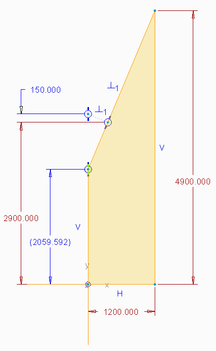
A little explanation: This sketch shows the side view of an eccentric cone. This cone is connected to a cylinder on the left and on the right side, as a part of a pressure vessel.
On the right side, the vessel diameter is 4900mm. On the left side, the vessel diameter is 2900mm. The cone length is 1200mm. All these fixed dimensions are locked (brown)
This is the cone in THEORY.
To weld the connection between the cone and the cylinder on the left side, we need an internal weld preparation. In the sketch, this weld preparation is oversized extremely to make it visible.
From the sloped line of the cone, a line normal to that line is drawn. This line is constrained 2 times: normal to the cone surface, and in line with the left side of the cone.
The point of this line on the cone will be our left cylinder diameter. (THEORETICAL VALUE)
The smaller value (2059.592mm in this case) is the ACTUAL diameter we will use to create the cone.
The weld preparation here in the screenshot is set to 150 mm to be visible. In reality, this weld preparation is only 5 mm.
Download this sketch, open it, and try to alter the weld preparation dimension (150mm) to the correct value of 5mm. By editing the dimension directly.
In most cases, this will not give the correct results. Reason: there are 2 possible solutions for this sketch.
To be able to alter this dimension to 5, you should drag the top point of the construction line slowly towards the correct dimension (let's say 5.65mm), and then you can alter the dimension to the correct value of 5mm.
If you want to draw this sketch only once, this small glitch won't annoy you most probably. But we are creating dynamic parts, driven by parameters and relations. And in this situation it is not desired to have these multiple solutions. If parameters are set, you cannot control which solution is chosen by Creo.
I think there is only 1 sketch solution, but I doubt it exists in Creo (or in any other drawing program):
- define a range of values a dimension can have (eg. 0 -> 5000mm / 35 -> 55° / only positive / ...)
I have now created a set of equations to calculate this sketch, and I put this in the relations of the part. This is the solution I currently use for this situation. And now it cannot fail anymore, since I 'm able to filter the wrong values. But this is a much more complex way of dealing with this kind of problems. I would rather just use a sketch to get my information.
The problem Ronald has, is similar, but in a 3D situation. Multiple solutions, but not possible to think of a definition to always get the right one.
Mar 01, 2013
12:46 PM
- Mark as New
- Bookmark
- Subscribe
- Mute
- Subscribe to RSS Feed
- Permalink
- Notify Moderator
Mar 01, 2013
12:46 PM
This "should not" be difficult at all. If I understand correctly, you want the point to be 5mm -outside- the angled line, right? The way the sketch is currently constrained, it has only one solution, right (bound by the coincident with the vertical line)? So make an analysis feature (simple measure length) of the construction line and dimension the "point" on that line with a relation of "Measure-5".
If I under stand correctly and the problem feature is the 5mm line, this should solve the problem of the short line flipping about the angled line.
Here is another trick that overcomes a serious problem with scaling sketches. The problem is making too big a jump from the previous version. You could, through relations, limit the amount a sketch is scaled by limiting the difference from step to step. Say you have a 1000mm dimension and changing this more than 100 at a time causes errors. You could force a relation to revert to the maximize the jump 100 only if the input is greater than this.
The only other problem I can see is that the sketch could flip the large angled line as well under some conditions. In this case too, you can place a dimension and have a relation test this condition to make sure the angle is within a range or some other construction geometry is within an expected range. If it fails, you can have it go to a default value or simply revert the change to the original value.
I know one shouldn't have to do this, but as one that has come to rely on sketches for some very stable scaling and evaluation, it -is- possible.
