
Turn on suggestions
Auto-suggest helps you quickly narrow down your search results by suggesting possible matches as you type.
Showing results for
Turn on suggestions
Auto-suggest helps you quickly narrow down your search results by suggesting possible matches as you type.
Showing results for
Community Tip - You can subscribe to a forum, label or individual post and receive email notifications when someone posts a new topic or reply. Learn more! X
- Community
- Creo+ and Creo Parametric
- 3D Part & Assembly Design
- Re: How to bend an extrusion with flexible modelin...
Options
- Subscribe to RSS Feed
- Mark Topic as New
- Mark Topic as Read
- Float this Topic for Current User
- Bookmark
- Subscribe
- Mute
- Printer Friendly Page
How to bend an extrusion with flexible modeling
May 29, 2015
11:28 AM
- Mark as New
- Bookmark
- Subscribe
- Mute
- Subscribe to RSS Feed
- Permalink
- Notify Moderator
May 29, 2015
11:28 AM
How to bend an extrusion with flexible modeling
Hallo,
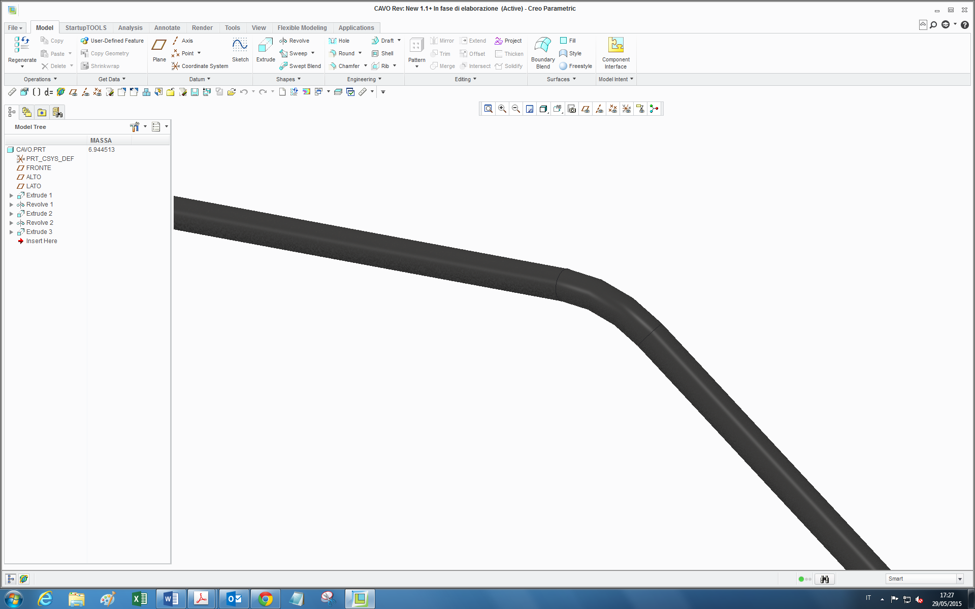
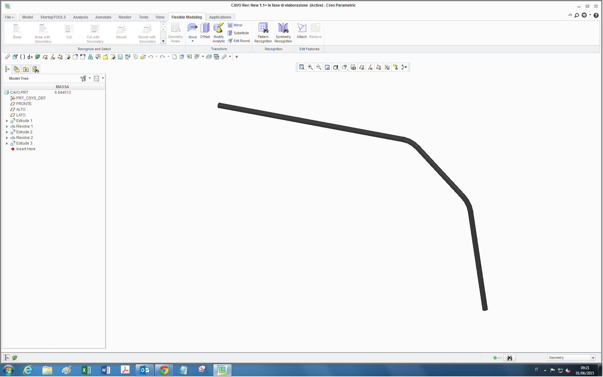
anyone has suggestions on how could I bend this pipe with flexible modeling to have a turn like this one below?:
thanks
bye
This thread is inactive and closed by the PTC Community Management Team. If you would like to provide a reply and re-open this thread, please notify the moderator and reference the thread. You may also use "Start a topic" button to ask a new question. Please be sure to include what version of the PTC product you are using so another community member knowledgeable about your version may be able to assist.
Labels:
- Labels:
-
General
21 REPLIES 21
May 29, 2015
02:01 PM
- Mark as New
- Bookmark
- Subscribe
- Mute
- Subscribe to RSS Feed
- Permalink
- Notify Moderator
May 29, 2015
02:01 PM
Flexible Modeling or Flexibility? What is the end result that you want to accomplish?
I have used Spinal Bend with Flexibility. See the excellent video by Leo Greene.
Pro/ENGINEER Wildfire Tutorial, Spinal Bend, Understanding the Possibilities - YouTube
Jun 01, 2015
03:43 AM
- Mark as New
- Bookmark
- Subscribe
- Mute
- Subscribe to RSS Feed
- Permalink
- Notify Moderator
Jun 01, 2015
03:43 AM
I mean with Flexible Modeling, maybe in some way it can be done, also because it seems to be quite a simple and basic operation:
Concerning the spinal bend: the problem of doing this bend (I didn't say it in the original post) with a normal revolution (as I did in the part you see in the screenshot) or with a spinal bend too I think, is that since I want to use it as flexible component to be put in an assembly (it is a cable rolling in pulleys) where the angle of that bending adapts to pulleys positions, when that angle shoud be zero (straight cable) the revolution is not able to go to zero, and all the assembly position messes up...
so I was wondering whether in someway a possible bend with flexible modeling might be set to zero in flexibility to achieve this when the requested angle should be zero...otherwise I have to turn on the straight piece and off the bend, but in this case these features turned off and on should be subject to conditions (if...then...) and it becomes I think more complex if not impossible in this way.
Jun 02, 2015
11:33 AM
- Mark as New
- Bookmark
- Subscribe
- Mute
- Subscribe to RSS Feed
- Permalink
- Notify Moderator
Jun 02, 2015
11:33 AM
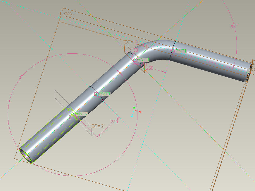
I know basics of flexible modeling. I think you cannot do with that. I think you can do with transitions made of curve+sweep between straight parts of tube. In this case you can do a transition with no round. Here an example with 1 round transition and 1 straight transition. I think to be clear. Piping module is what you need, i think.
Jun 03, 2015
09:08 AM
- Mark as New
- Bookmark
- Subscribe
- Mute
- Subscribe to RSS Feed
- Permalink
- Notify Moderator
Jun 03, 2015
09:08 AM
Hi Mauro,
thanks for your reply, I cannot have the pipe modulus as this is the only time this happened to me. I did not understand what you mean, would it be possible for you to make a screen recording ? (or also give the steps, as the only transition I have seen is the one in the round feature, but I suppose it is not what you are refering to)
thanks
Bye
Jun 03, 2015
09:41 AM
- Mark as New
- Bookmark
- Subscribe
- Mute
- Subscribe to RSS Feed
- Permalink
- Notify Moderator
Jun 03, 2015
09:41 AM
Tonight i will post the file Creo 3.0. Anyway in picture you see there's a straight zone and its lenght is 230mm. 0° angle for transition.
Jun 03, 2015
12:14 PM
- Mark as New
- Bookmark
- Subscribe
- Mute
- Subscribe to RSS Feed
- Permalink
- Notify Moderator
Jun 04, 2015
05:31 AM
- Mark as New
- Bookmark
- Subscribe
- Mute
- Subscribe to RSS Feed
- Permalink
- Notify Moderator
Jun 04, 2015
05:31 AM
Hi Mauro,
thanks a lot for you reply. However I forgot to tell you that I currently have Creo 2.0 M110, in fact the software does not open the file. 
Bye
Jun 04, 2015
11:47 AM
- Mark as New
- Bookmark
- Subscribe
- Mute
- Subscribe to RSS Feed
- Permalink
- Notify Moderator
Jun 04, 2015
11:47 AM
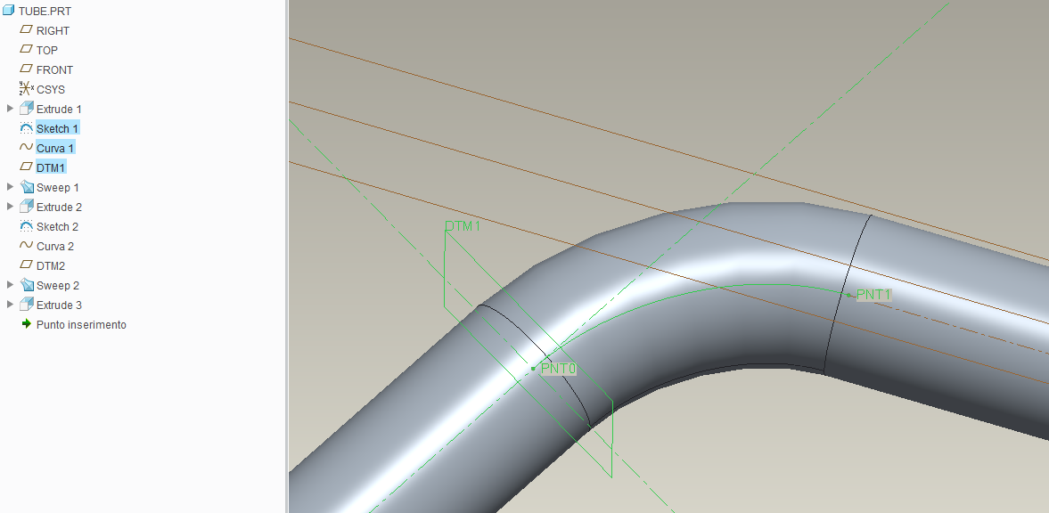
Attached file for Creo 2.0.
Try to see if it can be useful for you.
Jun 05, 2015
04:47 AM
- Mark as New
- Bookmark
- Subscribe
- Mute
- Subscribe to RSS Feed
- Permalink
- Notify Moderator
Jun 05, 2015
04:47 AM
Hi Mauro,
thanks a lot, now it's clear to me what you mean, and it's interesting indeed this way to pass from curve to straight.
It'a a pity that still remains the problem that the reference curve, from which you draw the sweep, cannot be set to follow a circle but only a spline, so it's not an arc indeed.
(neither one can trace a sketch with an arc from point to point, as it would go in error at angle zero)
bye bye
Jun 02, 2015
11:51 AM
- Mark as New
- Bookmark
- Subscribe
- Mute
- Subscribe to RSS Feed
- Permalink
- Notify Moderator
Jun 02, 2015
11:51 AM
You can make it a family table part, with the spinal bend feature resumed only at the assy level. Make sure to use a perimeter dimension and relations to control the length of the spinal bend spine, to make it = the regular extrusion length. Use the centerline of the tubing and let it compress or stretch offset the neutral axis.
Jun 03, 2015
08:34 AM
- Mark as New
- Bookmark
- Subscribe
- Mute
- Subscribe to RSS Feed
- Permalink
- Notify Moderator
Jun 03, 2015
08:34 AM
thanks for your reply.
But the problem I have is that at assembly level, the bend may be or may not be present, according to the angle the cable must have. I.e.: if the cable, once assembled, should be straight, the bend should disappear...or, if it was possible with flexible modeling, set the bend angle to zero.
Jun 03, 2015
10:20 AM
- Mark as New
- Bookmark
- Subscribe
- Mute
- Subscribe to RSS Feed
- Permalink
- Notify Moderator
Jun 03, 2015
10:20 AM
The main problem is there isn't an element in Creo that can have zero curvature without having only zero curvature. You can simulate this with a spline and move the control points around but that's not a curvature based control.
Even if you do a spinal bend, you run into the same problem - the path for the bend is made of elements that can either have zero curvature or a non-zero curvature.
I keep mentioning the need for a curvature element that would solve this and many other problems; rather than a radius that needs an infinite value to be straight and cannot be reversed, a curvature element can have any reasonable value, positive, negative, or zero to handle situations just like this. To make a sharp corner with a curvature element requires it to be zero length and infinite curvature, neither of which can happen with real materials, so a curvature element is very realistic.
The other problem, and one that is not easily solved, is arbitrary path mapping from a solid part to a path in an assembly. It would be ideal to establish a trajectory and orientation trajectory in the part and matching trajectories in the assembly and have Creo map/distort the geometry from one to the other. A feature much like this is in Blender, but it has to be built in and PTC has chosen not to do this.
Jun 04, 2015
12:11 PM
- Mark as New
- Bookmark
- Subscribe
- Mute
- Subscribe to RSS Feed
- Permalink
- Notify Moderator
Jun 04, 2015
12:11 PM
yes in fact the curvature collapsing in straight line is practically impossible in mathematics...(limit for radius -> infinite ) and this could the reason Creo cannot do this...maybe at this point if not with flexible modeling, maybe Creo Direct could do something in this way
Jun 04, 2015
12:16 PM
- Mark as New
- Bookmark
- Subscribe
- Mute
- Subscribe to RSS Feed
- Permalink
- Notify Moderator
Jun 04, 2015
12:16 PM
How about tweak things a little, so it ALMOST goes to zero? All it would take is .001, or even .0001 if your accuracy is set high enough.
Yeah, that limitation is a REAL drag. I ran into that on numerous occasions with VSS's (Variable Section Sweeps). Most recently on my ArAnCa loop, where I had to stop 1deg short on both halves of my unfold/refold, then put a patch in to tie it all together. It would have been SO much easier to just do it in one shot. Ah well, that's what you get when you divide by zero! 
Jun 05, 2015
04:57 AM
- Mark as New
- Bookmark
- Subscribe
- Mute
- Subscribe to RSS Feed
- Permalink
- Notify Moderator
Jun 05, 2015
04:57 AM
yes also, it could be done but I fear on long distances that almost zero error propagates and becomes non-negligeable....and yes, this is one thing that, like some others in Creo, would be a real "manna from heaven"...
Jun 04, 2015
12:35 PM
- Mark as New
- Bookmark
- Subscribe
- Mute
- Subscribe to RSS Feed
- Permalink
- Notify Moderator
Jun 04, 2015
12:35 PM
You can use a spline ... not as easy as a curvature controlled element, but possible.
Jun 05, 2015
05:00 AM
- Mark as New
- Bookmark
- Subscribe
- Mute
- Subscribe to RSS Feed
- Permalink
- Notify Moderator
Jun 05, 2015
05:00 AM
Hi David,
yes also, it is the way Mauro did it but at this point it would not an arc anymore, especially at high turn angles...
Jun 03, 2015
10:22 AM
- Mark as New
- Bookmark
- Subscribe
- Mute
- Subscribe to RSS Feed
- Permalink
- Notify Moderator
Jun 03, 2015
10:22 AM
Then assemble the straight instance at the assembly level.
Jun 04, 2015
05:33 AM
- Mark as New
- Bookmark
- Subscribe
- Mute
- Subscribe to RSS Feed
- Permalink
- Notify Moderator
Jun 04, 2015
05:33 AM
Hi Frank,
the commodity would be to have the cable auto-updating its curvature/bend when you change the winding angle of the cable around the pulley in my case...otherwise as you said I have to re-assemble it each time...
bye
Jun 04, 2015
10:22 AM
- Mark as New
- Bookmark
- Subscribe
- Mute
- Subscribe to RSS Feed
- Permalink
- Notify Moderator
Jun 04, 2015
10:22 AM
Ahhh, that complicates things. Without seeing the assy, it's kinda hard to help, Paisan.
Jun 04, 2015
10:26 AM
- Mark as New
- Bookmark
- Subscribe
- Mute
- Subscribe to RSS Feed
- Permalink
- Notify Moderator
Jun 04, 2015
10:26 AM
Yes in fact I managed to do it but....except for angle zero!
