
Turn on suggestions
Auto-suggest helps you quickly narrow down your search results by suggesting possible matches as you type.
Showing results for
Turn on suggestions
Auto-suggest helps you quickly narrow down your search results by suggesting possible matches as you type.
Showing results for
Community Tip - You can change your system assigned username to something more personal in your community settings. X
- Community
- Creo+ and Creo Parametric
- 3D Part & Assembly Design
- How to created a variable surface around a cilinde...
Options
- Subscribe to RSS Feed
- Mark Topic as New
- Mark Topic as Read
- Float this Topic for Current User
- Bookmark
- Subscribe
- Mute
- Printer Friendly Page
How to created a variable surface around a cilinder with an irregular path
Oct 10, 2014
03:03 PM
- Mark as New
- Bookmark
- Subscribe
- Mute
- Subscribe to RSS Feed
- Permalink
- Notify Moderator
Oct 10, 2014
03:03 PM
How to created a variable surface around a cilinder with an irregular path
Hello, i would like your help please.
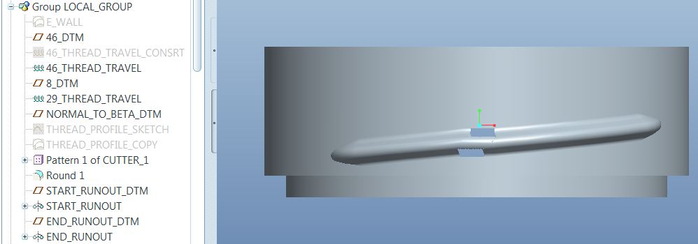
I am trying to improve the way to create a surface around a cilinder following a variable path. for example 40° going down 10° horizontal around then 15° going down.
I am using the helical sweep protusion tool, so, there is a pitch that brings a datum plane perpendicular to the trajectory (40° going down), a sketch that simulate the profile of the desired surface and an angle respect to the Top DTM, them the surface created need to do an horizontal travel (10°) around the cilinder but the section at this point is not the same as the begining of the helical surface (the machine tool keeps its angle respect to the Top DTM) it is not possible to take a vertical section to do a revolve.
Finally another helical sweep protusoin tool , the same pitch for the last 15° going down with the same profile as the begining.
For a better idea please see the attached image.
I have tryied using the wrap tool, but refences get lose.
This thread is inactive and closed by the PTC Community Management Team. If you would like to provide a reply and re-open this thread, please notify the moderator and reference the thread. You may also use "Start a topic" button to ask a new question. Please be sure to include what version of the PTC product you are using so another community member knowledgeable about your version may be able to assist.
8 REPLIES 8
Oct 10, 2014
06:53 PM
- Mark as New
- Bookmark
- Subscribe
- Mute
- Subscribe to RSS Feed
- Permalink
- Notify Moderator
Oct 10, 2014
06:53 PM
Hello Marcos and welcome to the forum.
I haver to say that both the explanation and the sketch give me no clue as to what you are trying to accomplish.
It sounds like you are attempting to create a cam surface along a cylinder.
Have you considered using an evalgraph for a variable sweep feature?
If you can show more clearly what you result is that you looking for, that may help.
Oct 16, 2014
01:12 PM
- Mark as New
- Bookmark
- Subscribe
- Mute
- Subscribe to RSS Feed
- Permalink
- Notify Moderator
Oct 16, 2014
01:12 PM
Thank you Antonius.
I am attaching an better image of what I need.
I have used the helical sweep, pattern tool (32 entities separated 0.25°, around the cilinder for 8° horizontal travel)and helical sweep again.
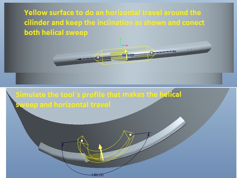
I wish this is a better explanation about what I am trying to do.
I have tried cutting surfaces and creating spline lines for a boundary surface that merge the horizontal travel to the helical sweeps, but it takes to much time.
- I believe, if the program can do the pattern with a small wide beween them, I bet that also has a tool to create this surfaces following the travel desired.
Thank you.
Oct 16, 2014
01:49 PM
- Mark as New
- Bookmark
- Subscribe
- Mute
- Subscribe to RSS Feed
- Permalink
- Notify Moderator
Oct 16, 2014
01:49 PM
I see. I would suggest forget the helical sweep and use a sweep. The entire featre can be made with a single sweep feature. You only a need a path (origin) to drive the section. That path can be made in many ways. The simplest way would be to intersect two sketches.
Oct 16, 2014
02:57 PM
- Mark as New
- Bookmark
- Subscribe
- Mute
- Subscribe to RSS Feed
- Permalink
- Notify Moderator
Oct 16, 2014
02:57 PM
I have tryied that way too, the problem is to determine exactly the section of the tool for the horizontal sketch, many reasons why program can not do that-
I am expecting for a suggestion in advanced tools and the way I have to do. For example Bend solid or others.
Thanks
Oct 16, 2014
03:13 PM
- Mark as New
- Bookmark
- Subscribe
- Mute
- Subscribe to RSS Feed
- Permalink
- Notify Moderator
Oct 16, 2014
03:13 PM
Calculations can be made within the sketch to determine the horizontal section based on radii and angles.
Sketches are very powerful as long as you apply the known data in a geometric way.
In this case, a wrap feature may also be useful as it preserves lengths.
As a hint, I often have to refer to arc lengths within a flat sketch. I simply create the relation that does the math to convert the perimeter to lengths using Pi*D/(n) relations in length values. Sketches are extremely powerful.
Use reference geometry extensively is you need a projection references. Concentrate on building the sweep path. Once you get that defined, the rest is simple. For projected references, you can wrap and project back if you intersect more comlex shapes. Again, I would not try to do this with a helical sweep.
Oct 16, 2014
03:16 PM
- Mark as New
- Bookmark
- Subscribe
- Mute
- Subscribe to RSS Feed
- Permalink
- Notify Moderator
Oct 16, 2014
03:16 PM
Also, how do you want to terminate the 2 ends of the segment?
Oct 16, 2014
03:38 PM
- Mark as New
- Bookmark
- Subscribe
- Mute
- Subscribe to RSS Feed
- Permalink
- Notify Moderator
Oct 16, 2014
03:38 PM
I did. it is close enought to have the proper profile. It takes almost the same time doing the cutting surfaces and merges etc.
I think this is the way (sweep paths), for sure I need to concentrate more on projected references.
About the 2 ends it is pretty easy, they are only revolves inside the cilinder.
Thank you.
Oct 16, 2014
03:54 PM
- Mark as New
- Bookmark
- Subscribe
- Mute
- Subscribe to RSS Feed
- Permalink
- Notify Moderator
Oct 16, 2014
03:54 PM
One thing to be aware of as your original post talks about it:
You can manage the orientation of the sweep in a fixed direction optionally so that is no problem.
However, a helical profile, regardless of how it is created, is very dependent on the tool shape. If you are using a rotary tool, it is a 3D object and the profiles we cut are 2D. The leading and trailing edges of the tool are not considered in your profile sketch. This is an awareness that may come to light. One way to check that your geometry accurately represents the tooling requirement is to make a cut of the tool shape (revolve/remove) and pattern it along your sweep path. If it takes material away, the 3D shape of the tool must be accounted for.
This is easily noticed with a gear hob. Although the hob profile has straight faces, the result is an involute gear tooth. Creo doesn't compensate for this on its own. Some profiles we can adjust, other require extensive support geometry depending on complexity. I only mention this in case you use a rapid prototype of this or expect to do analysis on the shape that does not meet the fabrication expectations of the final part.

