Turn on suggestions
Auto-suggest helps you quickly narrow down your search results by suggesting possible matches as you type.
Showing results for
Turn on suggestions
Auto-suggest helps you quickly narrow down your search results by suggesting possible matches as you type.
Showing results for
Community Tip - You can Bookmark boards, posts or articles that you'd like to access again easily! X
- Community
- Creo+ and Creo Parametric
- 3D Part & Assembly Design
- Re: How to make a analysis on oak
Options
- Subscribe to RSS Feed
- Mark Topic as New
- Mark Topic as Read
- Float this Topic for Current User
- Bookmark
- Subscribe
- Mute
- Printer Friendly Page
How to make a analysis on oak
Mar 15, 2016
09:23 AM
- Mark as New
- Bookmark
- Subscribe
- Mute
- Subscribe to RSS Feed
- Permalink
- Notify Moderator
Mar 15, 2016
09:23 AM
How to make a analysis on oak
Dear,
I am trying to make a analysis of a oak beam in Creo ptc.
I draw the beam, made a new material with the oak properties and give it constraint and loads.
But I get strange result out of it if I compare it with other programs like Inventor and Ansys.
I hope somebody can help me.
Thanks beforehands
Kinds regards
Oona
This thread is inactive and closed by the PTC Community Management Team. If you would like to provide a reply and re-open this thread, please notify the moderator and reference the thread. You may also use "Start a topic" button to ask a new question. Please be sure to include what version of the PTC product you are using so another community member knowledgeable about your version may be able to assist.
Labels:
- Labels:
-
General
14 REPLIES 14
Mar 15, 2016
09:50 AM
- Mark as New
- Bookmark
- Subscribe
- Mute
- Subscribe to RSS Feed
- Permalink
- Notify Moderator
Mar 15, 2016
09:50 AM
You will need to give more information that this, if you want us to help you!
What does your model look like? Ideally you can maybe share your model so we can have a look at it.
What is strange about the results?
What is the difference with Inventor / Ansys?
Mar 15, 2016
05:54 PM
- Mark as New
- Bookmark
- Subscribe
- Mute
- Subscribe to RSS Feed
- Permalink
- Notify Moderator
Mar 15, 2016
05:54 PM
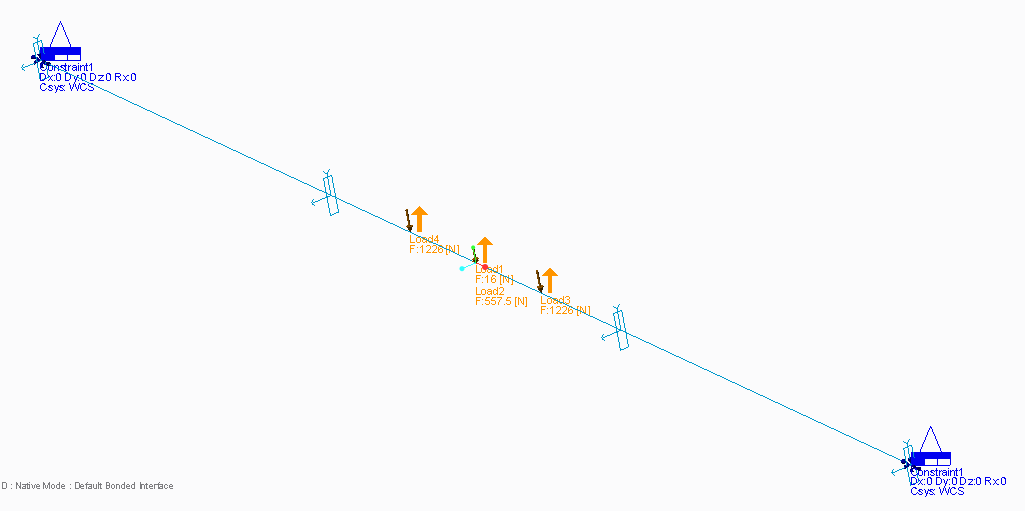
It is a oak beam of 48x200x8000mm there are 4 forces on it.
2 in the middle of 557.5N and 16N
And 2 remote forces at 48x200x3400mm and 48x200x4600mm of 1225.6N
The result with Ansys is 13mm, with Inventor is 17mm and with Creo ptc 23mm.
This is a quiet big difference.
I would like to add my document but I have now idea how.
Kinds regards
Oona
Mar 16, 2016
08:56 AM
- Mark as New
- Bookmark
- Subscribe
- Mute
- Subscribe to RSS Feed
- Permalink
- Notify Moderator
Mar 16, 2016
08:56 AM
Without knowing anything more, I would guess that the models created in ANSYS and Inventor are too stiff because the number of elements used are too small. Try increasing the number of elements in your beam to see if the result approaches the Simulate model.
Chris
Mar 16, 2016
09:06 AM
- Mark as New
- Bookmark
- Subscribe
- Mute
- Subscribe to RSS Feed
- Permalink
- Notify Moderator
Mar 16, 2016
09:06 AM
Hello
Cannot open your file, you are with a student version.
Kind regards.
Denis
Mar 16, 2016
01:56 PM
- Mark as New
- Bookmark
- Subscribe
- Mute
- Subscribe to RSS Feed
- Permalink
- Notify Moderator
Mar 16, 2016
01:56 PM
Dear
How can you increas the number of elements in Creo PTC simulation?
I only have a student version available.
Kinds regards
Mar 16, 2016
05:01 PM
- Mark as New
- Bookmark
- Subscribe
- Mute
- Subscribe to RSS Feed
- Permalink
- Notify Moderator
Mar 16, 2016
05:01 PM
I cannot open your model, but if I interpret your data correctly, and use a simply supported beam with E=12.15GPa for Oak Wood, then hand calculations show the max deflection should be about 11.4 mm. 80.8 mm
Now i'm curious why Creo finds over twice that value.... most likely some modelling error though!
Mar 16, 2016
11:09 PM
- Mark as New
- Bookmark
- Subscribe
- Mute
- Subscribe to RSS Feed
- Permalink
- Notify Moderator
Mar 16, 2016
11:09 PM
I happen to be very well aware of the operation of these codes, having used ANSYS and Mechanica for over 20 years. In my original post, I suggested increasing the number of elements in the ANSYS and Inventor models (not Simulate) to see if those results will approach the Simulate answer. I have seen this issue dozens of times with beginners getting into FEA and using Mechanica/Simulate and then trying the same model with an h-element code. When they double the elements in the h-code tool, all of a sudden the answer matches Mechanica/Simulate...for a very good reason. Proper training and course work to understand the fundamentals of how FEA codes work should be sought after for anybody wanting to learn how to use FEA. Otherwise, it's a time-consuming way to make funny-looking colored images of parts.
Of course, there are many other reasons why the results are different, this is my first guess without knowing anything else.
Mar 16, 2016
11:34 PM
- Mark as New
- Bookmark
- Subscribe
- Mute
- Subscribe to RSS Feed
- Permalink
- Notify Moderator
Mar 16, 2016
11:34 PM
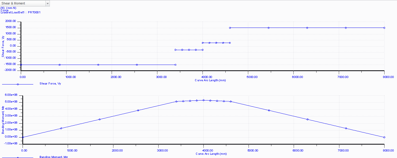
I must be misreading because the loads you have don't look like they cancel.
2 in the middle of 557.5N and 16N
And 2 remote forces at 48x200x3400mm and 48x200x4600mm of 1225.6N
Post a free-body diagram.
Mar 16, 2016
11:43 PM
- Mark as New
- Bookmark
- Subscribe
- Mute
- Subscribe to RSS Feed
- Permalink
- Notify Moderator
Mar 16, 2016
11:43 PM
Check h-Method & p-Method | Everyone is Number One for a better understanding of how the software you are using works and the suggestions being made.
Mar 18, 2016
08:57 AM
- Mark as New
- Bookmark
- Subscribe
- Mute
- Subscribe to RSS Feed
- Permalink
- Notify Moderator
Mar 18, 2016
08:57 AM
Dear,
Now the only thing I can do is following a small screen with the step materials, constraints, loads, analysis and view result.
Mine licence does not allow to us the upper toolbar.
Kinds regards
Mar 18, 2016
09:15 AM
- Mark as New
- Bookmark
- Subscribe
- Mute
- Subscribe to RSS Feed
- Permalink
- Notify Moderator
Mar 18, 2016
09:15 AM
Hello,
I am using the Academic Edition so I am able to see the beam.
Check the video for the solution of your problem.
Read while the video is loading...
Solution for Analysis and Simulation Question
Some comments/tips about the video and your problem:
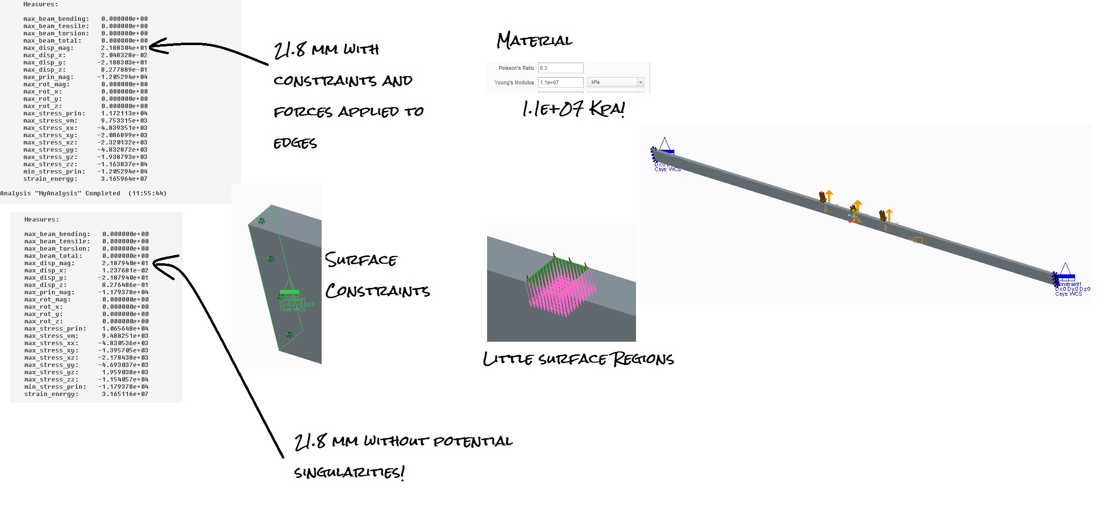
- The Academic Version allows to import simulation features from the Lite Version. I use the forces and constraints and create a new analysis. Based on your problem, I though it was better to use a surface and a shell idealization with 48 mm of thickness (in my opinion) and set simulate to 2D Plain Stress.
- To avoid point constraints (which can lead to singularities, and personal I don't like it) the two side edges were constrained.
- To avoid point forces (which can lead to singularities, and I don't like it either), three edges were sketched and constrained.
- Oak is not (by far) an isotropic material, so this is not a valid analysis for this material.
- To get the most accurate results, Measures were selected as Convergence Criteria.
- Notice how a simple problem reaches the 8th polynomial order when you select Measures as Convergence Criteria. Soon I will post a question about this, when you select Global RMS as convergence criteria, none of the measures (as stress) when you plot it against a graph has a visible convergence, mostly is always a straight line! Why? Notice in the video how convergence was reached by Global RMS and Measures are still to far of 8%. The safety factor will suffer the consequences or your processor should fried?
You are using the Lite Version. Try to apply this tips to your model (eliminate the load on the edges, create little regions or extrudes instead, avoid constraint points..)
Nice Friday to everybody. Sorry for the Spam, was a huge problem upload the video.
Mar 22, 2016
04:34 AM
- Mark as New
- Bookmark
- Subscribe
- Mute
- Subscribe to RSS Feed
- Permalink
- Notify Moderator
Mar 22, 2016
04:34 AM
I can't reproduce the 11.4mm now, but that site has some numbers already filled in by default, so that may have caused it.
For a simply supported beam I find 80.8mm. That is also what i find in Creo (81.0mm) and Abaqus (80.9mm) using beam sections on curves.
The difference must be in the constraints on the end points. My beams are "simply supported".
For a beam fully fixed at both ends, the hand calcs say 19.7mm, and Creo says 19.9 mm.
What constraints are you using to obtain 22mm Steven?
Mar 22, 2016
09:53 AM
- Mark as New
- Bookmark
- Subscribe
- Mute
- Subscribe to RSS Feed
- Permalink
- Notify Moderator
Mar 22, 2016
09:53 AM
I can't attach files here, so I opened a new Discussion here
There you can find my model, so maybe you can compare to yours?
Mar 24, 2016
01:18 PM
- Mark as New
- Bookmark
- Subscribe
- Mute
- Subscribe to RSS Feed
- Permalink
- Notify Moderator
Mar 24, 2016
01:18 PM
Translating the geometry to the Academic Version and avoiding singularities
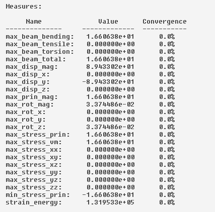
Gives the same result. 22 mm. According to the original constraints of the Lite Version, is fixed in all DOF and with free rotation in all direction (SOLID ELEMENTS, which does not support rotation, but well.. just info). Notice the values of Material Properties (KPA!)
Using Beam Idealization it gives 16.6 mm, but I am not sure if I constrained this correctly.