
Turn on suggestions
Auto-suggest helps you quickly narrow down your search results by suggesting possible matches as you type.
Showing results for
Turn on suggestions
Auto-suggest helps you quickly narrow down your search results by suggesting possible matches as you type.
Showing results for
Community Tip - Did you know you can set a signature that will be added to all your posts? Set it here! X
- Community
- Creo+ and Creo Parametric
- 3D Part & Assembly Design
- How to set certain perspective
Options
- Subscribe to RSS Feed
- Mark Topic as New
- Mark Topic as Read
- Float this Topic for Current User
- Bookmark
- Subscribe
- Mute
- Printer Friendly Page
How to set certain perspective
Jun 12, 2015
07:21 AM
- Mark as New
- Bookmark
- Subscribe
- Mute
- Subscribe to RSS Feed
- Permalink
- Notify Moderator
Jun 12, 2015
07:21 AM
How to set certain perspective
Hi,
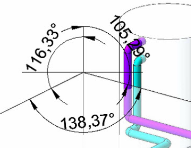
I need to create a view in a part, to be shown in a drawing, and it has to have certain pespective. It has to match an AutoCad drawing's perspective. I have measured the angles between the lines of the drawing, and these are the angles:
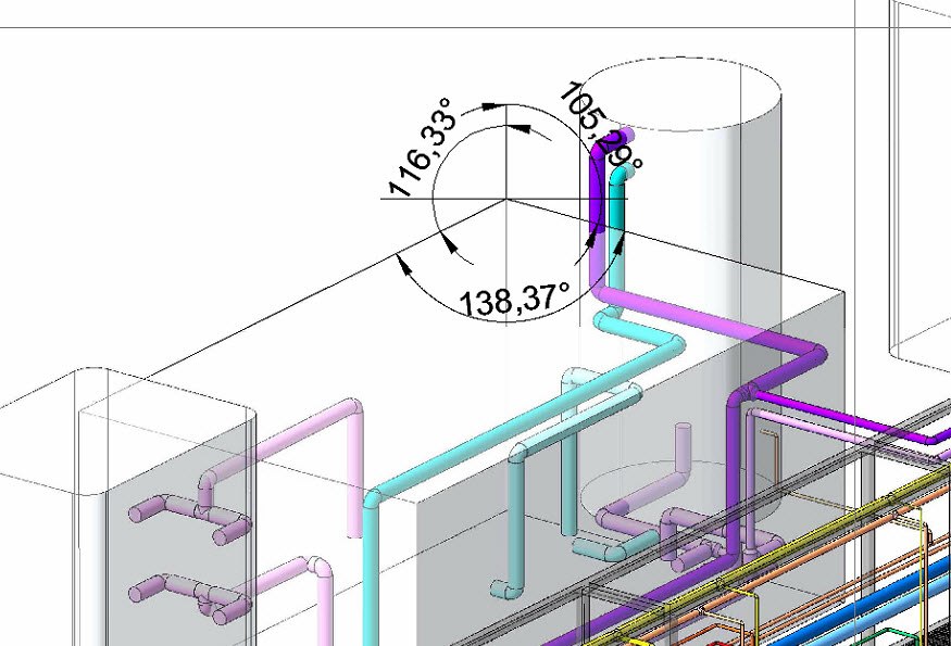
"138º, 116º, 106º"
But if I try to create a view rotating the part using thes angles, or any transformation (X-90º, 180º-X, ...) of these angles, I can't reach this perspective.
Anyone can help me with this?
Thank you very much!
This thread is inactive and closed by the PTC Community Management Team. If you would like to provide a reply and re-open this thread, please notify the moderator and reference the thread. You may also use "Start a topic" button to ask a new question. Please be sure to include what version of the PTC product you are using so another community member knowledgeable about your version may be able to assist.
Solved! Go to Solution.
Labels:
- Labels:
-
General
1 ACCEPTED SOLUTION
Accepted Solutions
Jun 12, 2015
09:02 PM
- Mark as New
- Bookmark
- Subscribe
- Mute
- Subscribe to RSS Feed
- Permalink
- Notify Moderator
Jun 12, 2015
09:02 PM
The uppercase formula is suitable for Excel; just omit the part ahead of the "=" sign. The turns are based on the original X axis to the right and the original Z axis pointing straight up; for me that is typically a Front view. It results in the Z axis foreshortened, but still projected vertical on the screen and the X axis above the horizon by alpha degrees and pointing back into the screen.
alpha and beta are the positive dihedral angles for the right and left sides. I used named cells for alpha and beta on the spreadsheet. You will see that if alpha = beta (both sides tilt the same, the vertical angle turn is always 45 degrees. I think it is alpha = /, right slope in drawing coordinates, and beta = \, left slope in coordinates. Any vertical line will remain vertical.
If you use some other method you may not need to use the Excel RADIANS and DEGREES conversion functions, but I did because I wanted to measure the angles in degrees and Excel only does trig functions in radians.
vertical angle = DEGREES(ATAN(SQRT(TAN(RADIANS(alpha))/TAN(RADIANS(beta)))))
horizontal angle = DEGREES(ASIN(SQRT(TAN(RADIANS(alpha))*TAN(RADIANS(beta)))))
12 REPLIES 12
Jun 12, 2015
07:52 AM
- Mark as New
- Bookmark
- Subscribe
- Mute
- Subscribe to RSS Feed
- Permalink
- Notify Moderator
Jun 12, 2015
07:52 AM
If I ever need a custom view, I create datums until I get a datum plane that can be selected as the front of my desired view. Are you allowed to add features to this model? If yes, then you can create datums with precise angle orientation. Create as many datums as you need to until you can create this custom view.
Jun 12, 2015
09:01 AM
- Mark as New
- Bookmark
- Subscribe
- Mute
- Subscribe to RSS Feed
- Permalink
- Notify Moderator
Jun 12, 2015
09:01 AM
I don't have the equations with me, but it's not too hard to derive them. Just imagine that there is a one unit line in the x and y directions and that there are two rotations, one about the vertical axis in the drawing and then the second along the horizontal axis. The trig will show how much each of those has to be to result in two of the angles shown. The third angle, by definition, is 360 minus the sum of the first two.
Tonight I'll look up the calc and post it if you don't have time.
Jun 12, 2015
10:18 AM
- Mark as New
- Bookmark
- Subscribe
- Mute
- Subscribe to RSS Feed
- Permalink
- Notify Moderator
Jun 12, 2015
10:18 AM
@ jstanczyk I can create additional features, datums, etc, but I don't see clearly which ones and how to create...
@dschenken I tried to rotate on 3 axis, but I don't get any good result. The hint I have is that on the target perspective, the edges are vertical, so I guess that I should start with the FRONT view (for example), the first rotate around the vertical axis, and then a second rotation around the horizontal axis of the screen. This way edges will stay vertical. The problem is that I don't know which angles to rotate...
Thank you for your help, I'll keep looking at it... 
New ideas are welcome!
Jun 12, 2015
11:55 AM
- Mark as New
- Bookmark
- Subscribe
- Mute
- Subscribe to RSS Feed
- Permalink
- Notify Moderator
Jun 12, 2015
11:55 AM
Yes - the vertical and horizontal rotation is the correct order. It's easy enough to figure out by drawing a front view and top view of 1 unit length lines rotated as you want to see them and then it's high school trigonometry to figure out the amount of rotation to get the model 1 unit length lines to have the same apparent angles as on the drawing.
It's good to work through the thought process, but I can send the answer later.
Jun 12, 2015
09:02 PM
- Mark as New
- Bookmark
- Subscribe
- Mute
- Subscribe to RSS Feed
- Permalink
- Notify Moderator
Jun 12, 2015
09:02 PM
The uppercase formula is suitable for Excel; just omit the part ahead of the "=" sign. The turns are based on the original X axis to the right and the original Z axis pointing straight up; for me that is typically a Front view. It results in the Z axis foreshortened, but still projected vertical on the screen and the X axis above the horizon by alpha degrees and pointing back into the screen.
alpha and beta are the positive dihedral angles for the right and left sides. I used named cells for alpha and beta on the spreadsheet. You will see that if alpha = beta (both sides tilt the same, the vertical angle turn is always 45 degrees. I think it is alpha = /, right slope in drawing coordinates, and beta = \, left slope in coordinates. Any vertical line will remain vertical.
If you use some other method you may not need to use the Excel RADIANS and DEGREES conversion functions, but I did because I wanted to measure the angles in degrees and Excel only does trig functions in radians.
vertical angle = DEGREES(ATAN(SQRT(TAN(RADIANS(alpha))/TAN(RADIANS(beta)))))
horizontal angle = DEGREES(ASIN(SQRT(TAN(RADIANS(alpha))*TAN(RADIANS(beta)))))
Jun 15, 2015
02:29 AM
- Mark as New
- Bookmark
- Subscribe
- Mute
- Subscribe to RSS Feed
- Permalink
- Notify Moderator
Jun 15, 2015
02:29 AM
David,
I tested your formulas. The second one failed, because value assigned to asin function was > 1.
I used alpha=105.29 and beta=116.33. Are these values correct for your formulas ?
Thanks in advance for your answer.
Martin Hanak
Martin Hanák
Jun 15, 2015
08:33 AM
- Mark as New
- Bookmark
- Subscribe
- Mute
- Subscribe to RSS Feed
- Permalink
- Notify Moderator
Jun 15, 2015
08:33 AM
The formulas are for angle above horizon, not angle from vertical.There is a left-side angle (beta) and a right-side angle (alpha)
Jun 15, 2015
08:41 AM
- Mark as New
- Bookmark
- Subscribe
- Mute
- Subscribe to RSS Feed
- Permalink
- Notify Moderator
Jun 15, 2015
08:41 AM
David,
I am sorry I still do not understand you. I do not know where is the horizon...
Please can you tell how to deduce alpha and beta angles for the above show picture ?
Thanks in advance for your answer.
Martin Hanak
Martin Hanák
Jun 15, 2015
08:43 AM
- Mark as New
- Bookmark
- Subscribe
- Mute
- Subscribe to RSS Feed
- Permalink
- Notify Moderator
Jun 15, 2015
08:43 AM
To be more specific for this case -
The 105 degree angle to the right and down corresponds to a 15 degree angle to the left and up - beta
The 116 degree angle to the left and down corresponds to a 26 degree angle to the right and up - alpha
The angle above horizon for the formula is chosen to match the way drafting was used to make isometric and trimetric views in the past, with sloped attachments on the t-square or drafting arm.
Jun 16, 2015
02:28 AM
- Mark as New
- Bookmark
- Subscribe
- Mute
- Subscribe to RSS Feed
- Permalink
- Notify Moderator
Jun 16, 2015
02:28 AM
David,
thanks for your patience . Your formulas now produce the appropriate values.
I was able to compute angle values using Creo 2.0 relation, too:
right_angle=105.29
left_angle=116.33
beta_angle=right_angle-90
alpha_angle=left_angle-90
vertical_angle=atan(sqrt(tan(alpha_angle)/tan(beta_angle)))
horizontal_angle=asin(sqrt(tan(alpha_angle)*tan(beta_angle)))
/* vertical_angle=53.378513
/* horizontal_angle=21.581245
Martin Hanak
Martin Hanák
Jun 19, 2015
04:22 AM
- Mark as New
- Bookmark
- Subscribe
- Mute
- Subscribe to RSS Feed
- Permalink
- Notify Moderator
Jun 19, 2015
04:22 AM
Thank you very much to all of you, you helped me a lot with this issue! 

Jun 12, 2015
10:53 AM
- Mark as New
- Bookmark
- Subscribe
- Mute
- Subscribe to RSS Feed
- Permalink
- Notify Moderator
Jun 12, 2015
10:53 AM
Just to point out this is an isometric view and not a perspective. A perspective has lines that angle to a vanishing point.
