
Turn on suggestions
Auto-suggest helps you quickly narrow down your search results by suggesting possible matches as you type.
Showing results for
Turn on suggestions
Auto-suggest helps you quickly narrow down your search results by suggesting possible matches as you type.
Showing results for
Community Tip - When posting, your subject should be specific and summarize your question. Here are some additional tips on asking a great question. X
- Community
- Creo+ and Creo Parametric
- 3D Part & Assembly Design
- Incorrect Flat pattern output when using flange in...
Options
- Subscribe to RSS Feed
- Mark Topic as New
- Mark Topic as Read
- Float this Topic for Current User
- Bookmark
- Subscribe
- Mute
- Printer Friendly Page
Incorrect Flat pattern output when using flange in sheetmetal
Feb 14, 2014
03:40 AM
- Mark as New
- Bookmark
- Subscribe
- Mute
- Subscribe to RSS Feed
- Permalink
- Notify Moderator
Feb 14, 2014
03:40 AM
Incorrect Flat pattern output when using flange in sheetmetal
Hi all new to the Forum hope you can help me with this problem
i have for years used the the flange command in sheet metal to create sheet metal mitred flanges.
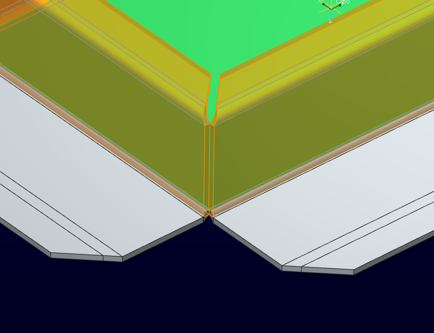
I have always just sent the flat patterns to the fabricator as dxf file and let them deal with the profiles of the flatpatterns in most cases proe/creo will add relief to the flanges which will curve the profile and for years this was ok but now the fabricator wants all relief to be straight on the mitre flanges i cant for the life of me get creo to give me an output without curves on the mitres
Any help on this would really be appreciated please see attached pics and file which will explain exactly what i am looking for
Thanks in Advance G
This thread is inactive and closed by the PTC Community Management Team. If you would like to provide a reply and re-open this thread, please notify the moderator and reference the thread. You may also use "Start a topic" button to ask a new question. Please be sure to include what version of the PTC product you are using so another community member knowledgeable about your version may be able to assist.
Labels:
- Labels:
-
General
7 REPLIES 7
Feb 18, 2014
04:05 PM
- Mark as New
- Bookmark
- Subscribe
- Mute
- Subscribe to RSS Feed
- Permalink
- Notify Moderator
Feb 18, 2014
04:05 PM
I tried to figure this out within the flange feature, but had no luck. I'm not sure how to acomplish what you're looking for other than unbending the part and cutting out those curved mitres. It's not an elegant solution, but it works.
Feb 18, 2014
08:41 PM
- Mark as New
- Bookmark
- Subscribe
- Mute
- Subscribe to RSS Feed
- Permalink
- Notify Moderator
Feb 18, 2014
08:41 PM
Welcome to the forum, Graham.
The "problem" is the gap definition. You have a zero gap on the side and the top and to do this right, it has to have the transition through that bend.
To do what you are asking for means you would have a small gap on the top flanges (the 45 miter) and no gap on the vertial edges.
So as Andrew said, "unbend" the part and miter the edge and then "bend back".
There might be more methods but from what I know today, it requires more than a single step.
Feb 19, 2014
04:11 AM
- Mark as New
- Bookmark
- Subscribe
- Mute
- Subscribe to RSS Feed
- Permalink
- Notify Moderator
Feb 19, 2014
04:11 AM
Guys thank you for the replies
I was really hoping that this was a simple box i havent ticked or a setting that i havent added. But unfortunatley unbending and cutting the mitre out and then bending back looses all the time that i saved using the flange command in the first place.
Because this material ranges from 1-3mm the curves that creo create are only a hinderance to the fabricator who punches and laser cuts these parts so a requirement for the 0 bend allowance and straight edges is a must in manufacture time.
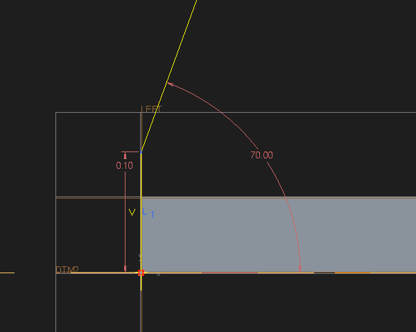
They K factor that is currently in use is 0.3 but the fabricator calculates the developed length and width by adding the inside bend dimensions.
the flange in the project is 50mm the inside lenght is 300mm and width 100mm
the bend dimensions on the flat pattern thus should measure the the same however they measure 100.71 and 50.36 respectivley, this leads me to belive that the incorrect flat pattern is used to achieve what the fabricator requires so i am going to change the k factor try and achive the correct bend dimensions i shall return to the forum later and let you guys know if this makes any differnce to flat result.
Again many thanks for your answers to this frustrating problem.
Feb 19, 2014
08:11 AM
- Mark as New
- Bookmark
- Subscribe
- Mute
- Subscribe to RSS Feed
- Permalink
- Notify Moderator
Feb 19, 2014
08:11 AM
You could also add a small flat portion to your flange. This doesn't help with the time portion of you problem, but would eliminate the curves when flat. As mentioned before, there isn't a quick 1-button way to eliminate this problem.
Feb 19, 2014
11:16 AM
- Mark as New
- Bookmark
- Subscribe
- Mute
- Subscribe to RSS Feed
- Permalink
- Notify Moderator
Feb 19, 2014
11:16 AM
Thanks James
Unfortunatley it seems this cant be done by changing settings which is a bit of a pain when the fabricator only has a punch and not a laser machine.
I solved the K factor problem by using the following K Factor 0.27 this gives me the correct distance between bend lines it calculates the flat size using the inside bend dimensions this what the fabricator requires.
I think i will have to design this using flatwalls and cut out the mitres
I guess this leads to another question what method do you guys use for creating internal and external mitres
at equal flange and unequal flange widths
Thanks for all your help
Feb 19, 2014
02:46 PM
- Mark as New
- Bookmark
- Subscribe
- Mute
- Subscribe to RSS Feed
- Permalink
- Notify Moderator
Feb 19, 2014
02:46 PM
First of all, the fab guys really would like a gap in that miter for the overbend required to get a true 90.
In all my years of sheetmetal work in various CAD systems, I've always worked with normal geometry by creating my own minimum bend relief, no sharps like the "V" notch, overlap as required by the design, etc. The job of the flat pattern was always left up to the shop since they know better. I had a requirement, and they made sure they met that with their internal allowances.
With the sheetmetal option in Creo, I would still use the software when it works for me. In the case you use, it is a great way to fold up 4 sides quickly with a flange. But I do go back and trim up the metal to my desired finished state in the flat. The thing that bothers me most in not having full control of the bend relief feature. For the most part it works fine, but you cannot tweak it in all cases because the bend back fails if you mess with this region.
Feb 19, 2014
02:49 PM
- Mark as New
- Bookmark
- Subscribe
- Mute
- Subscribe to RSS Feed
- Permalink
- Notify Moderator
