
Turn on suggestions
Auto-suggest helps you quickly narrow down your search results by suggesting possible matches as you type.
Showing results for
Turn on suggestions
Auto-suggest helps you quickly narrow down your search results by suggesting possible matches as you type.
Showing results for
Community Tip - Your Friends List is a way to easily have access to the community members that you interact with the most! X
- Community
- Creo+ and Creo Parametric
- 3D Part & Assembly Design
- Re: Maintaining profile orientation along complex ...
Options
- Subscribe to RSS Feed
- Mark Topic as New
- Mark Topic as Read
- Float this Topic for Current User
- Bookmark
- Subscribe
- Mute
- Printer Friendly Page
Maintaining profile orientation along complex path
Aug 17, 2014
09:05 PM
- Mark as New
- Bookmark
- Subscribe
- Mute
- Subscribe to RSS Feed
- Permalink
- Notify Moderator
Aug 17, 2014
09:05 PM
Maintaining profile orientation along complex path
I am trying to sweep a rectangular cut around a 3D profile, and I cannot figure out how to make Creo maintain the definition of vertical. The path is created by intersecting a swept helical surface and an extruded surface.
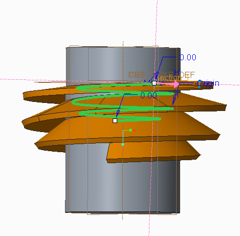
In the image above, I would like the rectangular profile to stay flat as it goes around the trajectory, but instead it is tilting downward. I would assume that the "Horizontal/Vertical control" drop-down in the references tab would let me correct this, but I'm only able to choose "Automatic".
I certainly appreciate any help. I've got 10 year of SolidWorks experience, but only a few days of Creo experience. I'm finding the online tutorials and help inadequate for learning how to create this feature. I'm attaching the model to this post, too.
This thread is inactive and closed by the PTC Community Management Team. If you would like to provide a reply and re-open this thread, please notify the moderator and reference the thread. You may also use "Start a topic" button to ask a new question. Please be sure to include what version of the PTC product you are using so another community member knowledgeable about your version may be able to assist.
Solved! Go to Solution.
1 ACCEPTED SOLUTION
Accepted Solutions
Aug 17, 2014
10:03 PM
- Mark as New
- Bookmark
- Subscribe
- Mute
- Subscribe to RSS Feed
- Permalink
- Notify Moderator
Aug 17, 2014
10:03 PM
Welcome to the forum, Greg.
Try making a secondary edge that can be used as a chain in conjunction with the origin or the sweep..
Here is a long cenveration on the subject but David cleared up your problem in the early posts:
16 REPLIES 16
Aug 17, 2014
10:03 PM
- Mark as New
- Bookmark
- Subscribe
- Mute
- Subscribe to RSS Feed
- Permalink
- Notify Moderator
Aug 17, 2014
10:03 PM
Welcome to the forum, Greg.
Try making a secondary edge that can be used as a chain in conjunction with the origin or the sweep..
Here is a long cenveration on the subject but David cleared up your problem in the early posts:
Aug 17, 2014
11:03 PM
- Mark as New
- Bookmark
- Subscribe
- Mute
- Subscribe to RSS Feed
- Permalink
- Notify Moderator
Aug 17, 2014
11:03 PM
Perfect. Thank you for the help. David's post worked exactly like I hoped.
-Greg
Aug 18, 2014
11:26 AM
- Mark as New
- Bookmark
- Subscribe
- Mute
- Subscribe to RSS Feed
- Permalink
- Notify Moderator
Aug 18, 2014
11:26 AM
Another solution maybe to use the "normal to projection" option. This maintains the section plane as normal to an imaginary curve that would be the result of the origin curve projected on the selected plane. In this case, you'd select a plane that is normal to your cylinder's axis.
Aug 18, 2014
12:41 PM
- Mark as New
- Bookmark
- Subscribe
- Mute
- Subscribe to RSS Feed
- Permalink
- Notify Moderator
Aug 18, 2014
12:41 PM
When used appropriately. Sadly, it is often used as a crutch because the normal to trajectory fails.
I believe a thread cut is an appropriate use for normal to projection.
Aug 18, 2014
01:23 PM
- Mark as New
- Bookmark
- Subscribe
- Mute
- Subscribe to RSS Feed
- Permalink
- Notify Moderator
Aug 18, 2014
01:23 PM
Most users that I've talked to don't know the option exists. I've found many uses for it in situations just like this and this is a perfect use for it, it would seem and would eliminate the need to create a second trajectory.
Aug 18, 2014
01:40 PM
- Mark as New
- Bookmark
- Subscribe
- Mute
- Subscribe to RSS Feed
- Permalink
- Notify Moderator
Aug 18, 2014
01:40 PM
...or that 
Aug 18, 2014
01:25 PM
- Mark as New
- Bookmark
- Subscribe
- Mute
- Subscribe to RSS Feed
- Permalink
- Notify Moderator
Aug 18, 2014
01:25 PM
Doug,
That is certainly more straightforward. However, it looks like this eliminates the constraint that the section plane is normal to the path, but instead it appears to be constructed between the cylindrical axis of the part and the point on the end of path. The sweep along the edge of a swept surface is thus better for my application as i require the section plane to be normal to the path.
Thanks.
Aug 18, 2014
01:40 PM
- Mark as New
- Bookmark
- Subscribe
- Mute
- Subscribe to RSS Feed
- Permalink
- Notify Moderator
Aug 18, 2014
01:40 PM
Right, for springs and things, you want normal to the path... for machine cuts, it is typically normal to the axis. You can always tell the difference with the sketch plane as long as there is a notable slope to the origin curve.
It does however complicate subsequent operations knowing the endpoint is not normal the standard planes. Knowing the difference and having the foresight will open new avenues.
Aug 18, 2014
01:40 PM
- Mark as New
- Bookmark
- Subscribe
- Mute
- Subscribe to RSS Feed
- Permalink
- Notify Moderator
Aug 18, 2014
01:40 PM
Ah, yes, this does redefine the section plane to be normal to the projection rather than normal to the origin.
I looked at David's solution and it went entirely over my head. If someone has the time to do a "for dummies" version, I'd love to hear it.
Aug 18, 2014
01:56 PM
- Mark as New
- Bookmark
- Subscribe
- Mute
- Subscribe to RSS Feed
- Permalink
- Notify Moderator
Aug 18, 2014
01:56 PM
It is pretty simple, Doug. In the cases I presented in the other discussion, the second Chain is simply an offset from the 1st. It maintains the x-direction of the sketch. It is a terrific way to assure the orientation of your newly created feature.
The problem comes when curves are highly dependent on how they are created to know what their orientation is. One of the worst conditions is when you create a cylindrical curve from equation, where the curve "twists" back to the CSYS it is defined from. If you use it for a spring with a round wire, you'd never know... but in my case, I used a square wire, and boom! Not acceptable!
So the re-definition, using the very same equation with a slightly larger R definition now guides the sweep with X pointing to the Chain (the second helix).
Now this is not without challenges, however. Continued efforts with this practice did have some odd behavior when the two came too close together. It actually jumps one loop and re-oriented the X at a diagonal. Easy to see, but if you have a very dynamic part (table driven or alike), you could end up with a bad instance. It doesn't necessarily fail, but it is not what you'd expect.
The take-away is that if you sweep a surface to create an edge, you might consider sweeping it to create 2 edges or intersecting a second surface. That way you have an X-direction for the secondary path (Chain).
Aug 19, 2014
08:48 AM
- Mark as New
- Bookmark
- Subscribe
- Mute
- Subscribe to RSS Feed
- Permalink
- Notify Moderator
Aug 19, 2014
08:48 AM
Thanks, I understand the concept of creating an X trajectory horizontally offset from the original, it was the equations that are throwing me off.
I'm not sure I've ever had the need to create a curve from an equation and it's not easy for me to follow. Complex geometry? Bring it on, no problem. Curve from equation? That makes my brain hurt. 😛
If I'm understanding correctly, this solution is specific to helix type curves driven by an equation where it's fairly easy to alter the equation to create another identical curve, but larger in "diameter", correct?
Aug 19, 2014
11:09 AM
- Mark as New
- Bookmark
- Subscribe
- Mute
- Subscribe to RSS Feed
- Permalink
- Notify Moderator
Aug 19, 2014
11:09 AM
http://communities.ptc.com/docs/DOC-3063
Just a sample for Curve<Equation<Graph. Notice the version where the spring reverses direction halfway.
It is simple to have a curve driven by an equation R=function and then another curve driven by R=function+deltaR.
The main thing is that the solid will only extend as far as there is control from both the original and x-direction trajectories. If the original makes 3 turns and the x-direction only one, then the solid will only make one turn.
Aug 19, 2014
03:22 PM
- Mark as New
- Bookmark
- Subscribe
- Mute
- Subscribe to RSS Feed
- Permalink
- Notify Moderator
Aug 19, 2014
03:22 PM
Yep, what ^HE^ said
Equation curves are worth understanding when you want so control things to follow specific "curves"; for instance, it is very difficult to define a spline as a true sine sweep. Equations solve this easily. The curve from equation is no different than using trajpar in a VSS with a "function" within it. These are just different ways to communicate the data. As a matter of fact, the curve from equation is simply a relation driven feature. And you have 3 types. The Cartesian is a simple X, Y, and Z data collector. The cylindrical curve requires a Radius, angle (Theta) and Z component. Spherical is pretty much radius, angle, angle. You can operate anything you want on these variables prior to specifying these, but you need a T component to give it length. Trajpar for instance is a T component with a value of 0 to 1, but curve from equation can have T be -1 to 2 for instance (total of 3 but not necessarily starting at 0). This is what give these features a perimeter, or length; geometric definision from an algebraic expression. Using evalgraph for a swept feature, for instance, does the same thing, it inputs variable data... if X=n then Y=n(graph).
In this discussion, anything you do to create the 1st curve/edge for the sweep you can scale R to get a constrained X-direction. Most of our discussions seem to center on conics... which are generically cylindrical (defined about an axis).
I find very little use in my line of work for these types of features. Springs, however are a different matter. Making springs do what you want when you want is something that is very specialized for making presentations and sets my work apart from others. Using equations in mechanism too bring life to presentations where you can have slow start motors, hold functions and alike. Going beyond the default 10 second single motion of a servo motor for instance is something you have to "program" (user defined). Once you get better at converting basic expressions into code, you can adapt it to other places within Creo once you figure out the syntax of that feature and what kind of feature it can be applied to. From a demonstration perspective, you really need some specific use-cases to show the commonality in the root of the equation.
Creo is a messy tool box. Once you know the tools within it, you can create wonderous things.
Aug 19, 2014
03:50 PM
- Mark as New
- Bookmark
- Subscribe
- Mute
- Subscribe to RSS Feed
- Permalink
- Notify Moderator
Aug 19, 2014
03:50 PM
And yes, David's example brings home the point that the "curve from equation" is almost a misnomer...and that it is indeed a "curve from relations"... with specific input requirements.
r =evalgraph("radius",t*16)
theta = 360*evalgraph("turns",t*16)
z=16*t
Aug 19, 2014
04:05 PM
- Mark as New
- Bookmark
- Subscribe
- Mute
- Subscribe to RSS Feed
- Permalink
- Notify Moderator
Aug 19, 2014
04:05 PM
As they all depend on the parameter "t," those are three parametric equations.
Here's what I found about mathematical relations: http://www.purplemath.com/modules/fcns.htm
"A "relation" is just a relationship between sets of information" Equations that map one domain to another are relations. A phone book is also a relation.
Aug 19, 2014
09:26 PM
- Mark as New
- Bookmark
- Subscribe
- Mute
- Subscribe to RSS Feed
- Permalink
- Notify Moderator
Aug 19, 2014
09:26 PM
"I did not have sexual relations with that woman!"

