Community Tip - Stay updated on what is happening on the PTC Community by subscribing to PTC Community Announcements. X
- Community
- Creo+ and Creo Parametric
- 3D Part & Assembly Design
- Make spiral casing
- Subscribe to RSS Feed
- Mark Topic as New
- Mark Topic as Read
- Float this Topic for Current User
- Bookmark
- Subscribe
- Mute
- Printer Friendly Page
Make spiral casing
- Mark as New
- Bookmark
- Subscribe
- Mute
- Subscribe to RSS Feed
- Permalink
- Notify Moderator
Make spiral casing
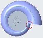
For about two weeks I am trying to make this for my project-
I have tried Sweep, sweep blend, boundary blend and other approaches.
But result is not satisfactory.
How can I do it?
Solved! Go to Solution.
- Labels:
-
General
Accepted Solutions
- Mark as New
- Bookmark
- Subscribe
- Mute
- Subscribe to RSS Feed
- Permalink
- Notify Moderator
1. I didn't remove any section, I did something similar to that shown in your second sketch. I made a solid spiral, not a surface.
2. If your spiral was a solid it would have a flat face. You could use that face to extrude a cylinder normal to the face. This means there will be a small cusp between the cylindrical feature and the spiral (no tangency).
3. I made everything solid and created a shell feature afterwards.
4. I don't know how to answer that.
5. The intersecting cylinder is simply sketched on the plane that is perpendicular to the axis of the spiral and extruded in both directions. It was created as a solid before the shell feature. Rounds were added at the end.
The model I created was put together very quickly and likely not the best solution.
- Mark as New
- Bookmark
- Subscribe
- Mute
- Subscribe to RSS Feed
- Permalink
- Notify Moderator
Simple, use a sweep with 2 guide curves, make sure the variable section option is set, the section will be a circle, and make sure you constrain the 2 quadrants 180deg apart to both of the trajectories "reference".
The trajectory curves can be sketched or curves via equation, or use a single curve and make the diameter a function of trajpar, or there are a couple other ways....
- Mark as New
- Bookmark
- Subscribe
- Mute
- Subscribe to RSS Feed
- Permalink
- Notify Moderator
I'll name that tune with one guide curve 🙂
Frank's right. Sweep with the VSS option... an origin curve for one end and a guide curve for the outer periphery. Sweep a variable circle/shape using both references.
- Mark as New
- Bookmark
- Subscribe
- Mute
- Subscribe to RSS Feed
- Permalink
- Notify Moderator
Based on the suggestion provided by @Patriot_1776, using curves defined by equation in this case.

- Mark as New
- Bookmark
- Subscribe
- Mute
- Subscribe to RSS Feed
- Permalink
- Notify Moderator
Yup! As mentioned, there are several ways. You can use a single trajectory as the guide, and use trajpar at the section level if you you want a straight linear change in diameter, or......do other things.....
- Mark as New
- Bookmark
- Subscribe
- Mute
- Subscribe to RSS Feed
- Permalink
- Notify Moderator
I used equations in this case to get a quick model approximating the shape of features shown in the original screenshot.
I'd probably sketch the trajectories for most sweeps, but I don't create swept features very often. Mostly parts with prismatic and cylindrical features, and assemblies. Sometimes more complex geometric forms, but I often have to try things out, experiment, research, learn from others and refine.
- Mark as New
- Bookmark
- Subscribe
- Mute
- Subscribe to RSS Feed
- Permalink
- Notify Moderator
Haven't done it in a long while, but the VSS feature probably still has controls that allow a particular cross-sectional area, say, if there were flow considerations and you needed a particular expansion rate. You could use a VSS to create an exponential horn for a speaker, for instance.
- Mark as New
- Bookmark
- Subscribe
- Mute
- Subscribe to RSS Feed
- Permalink
- Notify Moderator
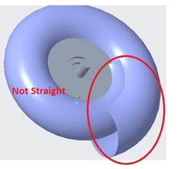
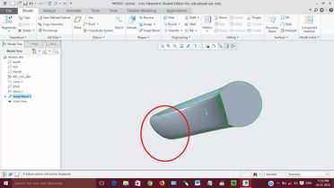
1- How did you remove section from here? for spiral guide path it is intersecting.
2-How did you bring penstock out straight? I am using spiral trajectory. So it is not straight. Spiral is drawn using equation. To get straight portion out of spiral what shuld I do?
3-Did you use extrude remove material to make hole?
4-Also what's wrong with this? edge is not vertical it is different file with ellipse at one end..
5-What is technique for the perfect intersecting cylinder?
Thanks for reply
- Mark as New
- Bookmark
- Subscribe
- Mute
- Subscribe to RSS Feed
- Permalink
- Notify Moderator
1. I didn't remove any section, I did something similar to that shown in your second sketch. I made a solid spiral, not a surface.
2. If your spiral was a solid it would have a flat face. You could use that face to extrude a cylinder normal to the face. This means there will be a small cusp between the cylindrical feature and the spiral (no tangency).
3. I made everything solid and created a shell feature afterwards.
4. I don't know how to answer that.
5. The intersecting cylinder is simply sketched on the plane that is perpendicular to the axis of the spiral and extruded in both directions. It was created as a solid before the shell feature. Rounds were added at the end.
The model I created was put together very quickly and likely not the best solution.
- Mark as New
- Bookmark
- Subscribe
- Mute
- Subscribe to RSS Feed
- Permalink
- Notify Moderator
Thank you again for your replies.
- Mark as New
- Bookmark
- Subscribe
- Mute
- Subscribe to RSS Feed
- Permalink
- Notify Moderator
Ha Ha, Please don't call me an expert, I'm far removed from the finished article.
- Mark as New
- Bookmark
- Subscribe
- Mute
- Subscribe to RSS Feed
- Permalink
- Notify Moderator
@manishdasariya, I came across this picture in an old book (c.1934) Engineering Wonders. It reminded me of your snail 🐵


