
Turn on suggestions
Auto-suggest helps you quickly narrow down your search results by suggesting possible matches as you type.
Showing results for
Turn on suggestions
Auto-suggest helps you quickly narrow down your search results by suggesting possible matches as you type.
Showing results for
Community Tip - Stay updated on what is happening on the PTC Community by subscribing to PTC Community Announcements. X
- Community
- Creo+ and Creo Parametric
- 3D Part & Assembly Design
- Merge Pieces Inquiry
Options
- Subscribe to RSS Feed
- Mark Topic as New
- Mark Topic as Read
- Float this Topic for Current User
- Bookmark
- Subscribe
- Mute
- Printer Friendly Page
Merge Pieces Inquiry
Aug 07, 2019
11:56 AM
- Mark as New
- Bookmark
- Subscribe
- Mute
- Subscribe to RSS Feed
- Permalink
- Notify Moderator
Aug 07, 2019
11:56 AM
Merge Pieces Inquiry
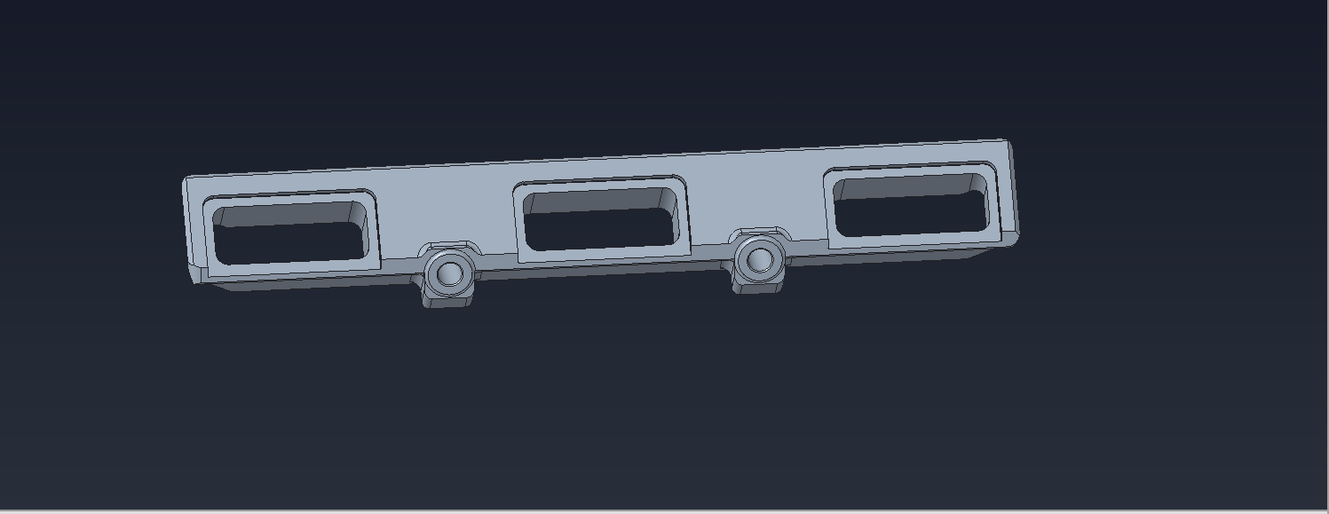
I was wondering if there is a feature in Creo Parametric 5 that will let a user to take a component (extruded in the center to remove excess cavities), shown in image 1, and merge them to replicate the one shown in image 2. I modified a longer rail system and would like to just remove the material so that I don't have to recreate all the features in the smaller piece.
Solved! Go to Solution.
Labels:
- Labels:
-
General
1 ACCEPTED SOLUTION
Accepted Solutions
Aug 09, 2019
04:37 AM
- Mark as New
- Bookmark
- Subscribe
- Mute
- Subscribe to RSS Feed
- Permalink
- Notify Moderator
Aug 09, 2019
04:37 AM
I'm not sure what you are really looking for here. Are you attempting to merge two components? or is the green model supposed to be a longer version (I don't get the huge gap between the two ends)?
There are a number of ways to create the second (grey) part from the first. Are you new to parametric cad?
It looks like you could create the rectangular cut with recess and rounds, group the feature and pattern to create any number of these cuts at variable pitches. If you do in one model these can be copied and pasted from one model to next so you only have to worry about matching references and then pattern in new model. There are other ways but hope this is a help.
3 REPLIES 3
Aug 07, 2019
02:59 PM
- Mark as New
- Bookmark
- Subscribe
- Mute
- Subscribe to RSS Feed
- Permalink
- Notify Moderator
Aug 07, 2019
02:59 PM
There is the flexible modeling tab. You can "move" geometry. This is direct modeling modification.
First, window select the area you want to move then select move, there are some options for "dragger move" or dimensional or constraint type.
It might take some experimentation to get it right. I personally wouldn't use this method for production type work, but for quick and dirty concepts, it works great!
Aug 09, 2019
04:37 AM
- Mark as New
- Bookmark
- Subscribe
- Mute
- Subscribe to RSS Feed
- Permalink
- Notify Moderator
Aug 09, 2019
04:37 AM
I'm not sure what you are really looking for here. Are you attempting to merge two components? or is the green model supposed to be a longer version (I don't get the huge gap between the two ends)?
There are a number of ways to create the second (grey) part from the first. Are you new to parametric cad?
It looks like you could create the rectangular cut with recess and rounds, group the feature and pattern to create any number of these cuts at variable pitches. If you do in one model these can be copied and pasted from one model to next so you only have to worry about matching references and then pattern in new model. There are other ways but hope this is a help.
Aug 13, 2019
12:01 PM
- Mark as New
- Bookmark
- Subscribe
- Mute
- Subscribe to RSS Feed
- Permalink
- Notify Moderator
Aug 13, 2019
12:01 PM
The green model is a longer version of the grey one. I extruded the portion out of the green model, as shown in the image, and was wondering if there was a way of connecting the two "floating" pieces left after the extrusion in the given part.
What I ended up doing was cutting the green piece to be equal to half of the grey one, mirrored the part, and created an assembly of both. I know it's not ideal, but it was a quick fix.
