
Turn on suggestions
Auto-suggest helps you quickly narrow down your search results by suggesting possible matches as you type.
Showing results for
Turn on suggestions
Auto-suggest helps you quickly narrow down your search results by suggesting possible matches as you type.
Showing results for
- Community
- Creo+ and Creo Parametric
- 3D Part & Assembly Design
- Re: Model to Help 5th Graders Understand PTC Coord...
Options
- Subscribe to RSS Feed
- Mark Topic as New
- Mark Topic as Read
- Float this Topic for Current User
- Bookmark
- Subscribe
- Mute
- Printer Friendly Page
Model to Help 5th Graders Understand PTC Coordinate System
Nov 20, 2016
04:14 PM
- Mark as New
- Bookmark
- Subscribe
- Mute
- Subscribe to RSS Feed
- Permalink
- Notify Moderator
Nov 20, 2016
04:14 PM
Model to Help 5th Graders Understand PTC Coordinate System
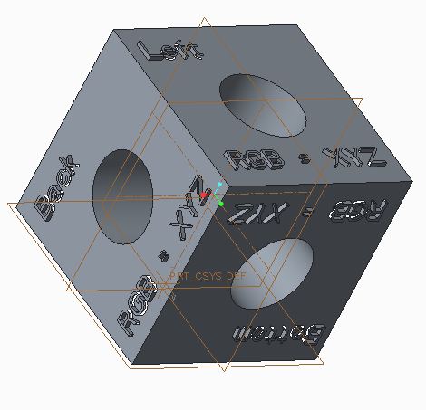
I've made the following model with which I hope to explain the PTC coordinate system to 5th Graders. I've succeeded only in confusing myself. Maybe you can help.
The file is attached. Created with Creo Parametric 3.0 M070 Academic. I think this a right hand system as pictured, I've extruded X+, X-. Y+, Y-, Z+ and Z-. I want to extrude (20mm) FRONT+, FRONT-, TOP+, TOP-, RIGHT+ and RIGHT_ on the planes I presume that FRONT+ is on the Y+ side of the FRONT plane. Am I on the right track?
It seems to me that the default system in Creo Academic is a left handed system!!!
This thread is inactive and closed by the PTC Community Management Team. If you would like to provide a reply and re-open this thread, please notify the moderator and reference the thread. You may also use "Start a topic" button to ask a new question. Please be sure to include what version of the PTC product you are using so another community member knowledgeable about your version may be able to assist.
Labels:
- Labels:
-
General
32 REPLIES 32
Nov 20, 2016
06:57 PM
- Mark as New
- Bookmark
- Subscribe
- Mute
- Subscribe to RSS Feed
- Permalink
- Notify Moderator
Nov 20, 2016
06:57 PM
The usual interpretation is that X is right, Z is up and Y is into the screen.
Right+ => X+,
Front+ => Y-
Top + => Z+
The names of the planes are arbitrary, but each coordinate system has labeled axes and Creo is entirely right-hand.
Nov 21, 2016
02:16 PM
- Mark as New
- Bookmark
- Subscribe
- Mute
- Subscribe to RSS Feed
- Permalink
- Notify Moderator
Nov 21, 2016
02:16 PM
Specifically for the Front orientation , X+ is right and Z+ is up on the screen. At least I consider it that way because the screen is typically vertical.
Nov 22, 2016
03:22 AM
- Mark as New
- Bookmark
- Subscribe
- Mute
- Subscribe to RSS Feed
- Permalink
- Notify Moderator
Nov 22, 2016
03:22 AM
Tentatively final models. I think these are correct. What do you think?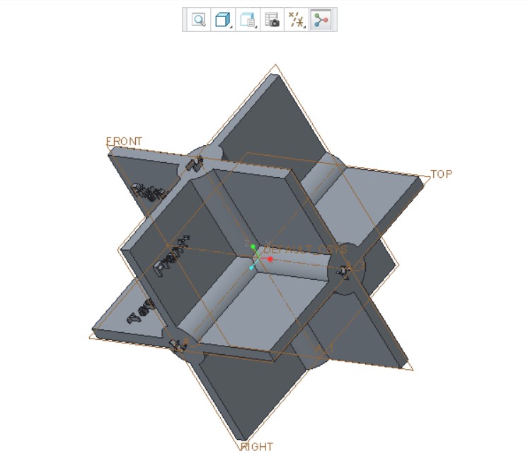
Both are right handed???
Nov 22, 2016
07:01 AM
- Mark as New
- Bookmark
- Subscribe
- Mute
- Subscribe to RSS Feed
- Permalink
- Notify Moderator
Nov 22, 2016
07:01 AM
Something is obviously screwed up with this model. The engraved planes don't agree with the brown PTC plane lines. Gr.
Back to the drawing board.
Nov 22, 2016
09:20 AM
- Mark as New
- Bookmark
- Subscribe
- Mute
- Subscribe to RSS Feed
- Permalink
- Notify Moderator
Nov 22, 2016
09:20 AM
Take a look at these comments from previous discussions. They should help you understand what Creo is doing and why.
Nov 22, 2016
10:51 AM
- Mark as New
- Bookmark
- Subscribe
- Mute
- Subscribe to RSS Feed
- Permalink
- Notify Moderator
Nov 22, 2016
10:51 AM
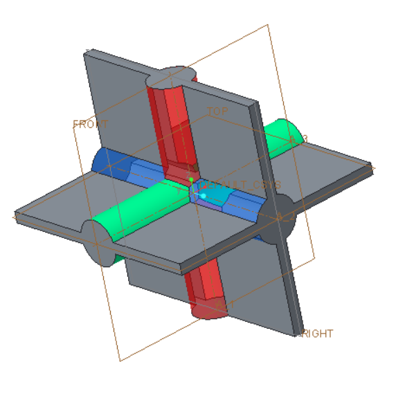
Thanks for all the help and references. I'm taking a new approach. COLORS! We will continue to gather information. How will I print a multicolored model???
More work to do.

Nov 22, 2016
08:19 AM
- Mark as New
- Bookmark
- Subscribe
- Mute
- Subscribe to RSS Feed
- Permalink
- Notify Moderator
Nov 22, 2016
08:19 AM
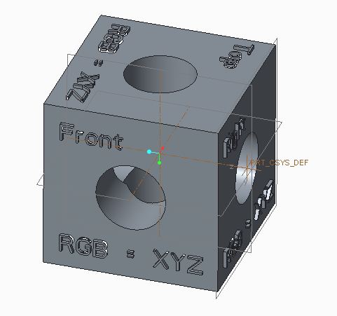
Your red-geen-blue triad isn't aligned to your xyz directions. ? I usually think red = X, green = Y, blue Z. RGB = XYZ - is that mnemonic familiar?
Anyway, it's all rather arbitrary, but this is how my start-parts and the default datum planes are aligned:
Nov 24, 2016
12:08 AM
- Mark as New
- Bookmark
- Subscribe
- Mute
- Subscribe to RSS Feed
- Permalink
- Notify Moderator
Nov 24, 2016
12:08 AM
Collected comments:
1. I need to build a color coded model
2. I need to assign colors correctly and place + and - signs on the gray axis ends. I also need to color the circular end caps of the axes.
3. In order to build a model with a single color 3D printer I will have to make it as an assembly consisting of the following parts:
a. 2 slotted red cylinders with one end shaped to fit into center.
b. 2 slotted green cylinders with one end shaped to fit into center.
c. 2 slotted blue cylinders with one end shaped to fit into center.
d. 12 gray squares
4. In addition to Top, Right and Front labels for 2D surfaces I will use the labels Bottom, Left, and Back which I have not seen in Creo, but which make sense to use.
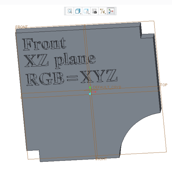
5. On each surface I will write the mnemonic "RGB=XYZ".
On my own I will have to figure out what is meant by "isometric" and "trimetric" and why isometric is the default. This is obviously not the first time coordinates have been discussed, but has anyone made a model? Many thanks for all the enlightening comments.
Nov 24, 2016
12:51 AM
- Mark as New
- Bookmark
- Subscribe
- Mute
- Subscribe to RSS Feed
- Permalink
- Notify Moderator
Nov 24, 2016
12:51 AM
Isometric projection - Wikipedia
In a trimetric projection, unit vectors projected onto the view plane are different lengths. In technical publication one axis is vertical, one is 15 degrees counter clockwise above horizontal and the other is 30 degrees clockwise above the horizontal axis.
Nov 24, 2016
01:36 AM
- Mark as New
- Bookmark
- Subscribe
- Mute
- Subscribe to RSS Feed
- Permalink
- Notify Moderator
Nov 24, 2016
01:36 AM
Hi,
if you have single color 3D printer, then I suggest you to print grey model and color it using brush and liquid colors  .
.
MH
Martin Hanák
Nov 24, 2016
02:26 AM
- Mark as New
- Bookmark
- Subscribe
- Mute
- Subscribe to RSS Feed
- Permalink
- Notify Moderator
Nov 24, 2016
02:26 AM
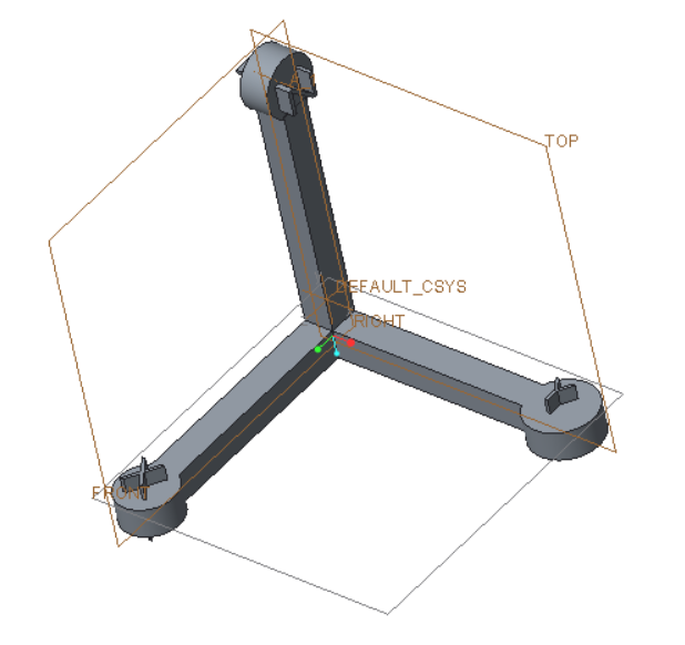
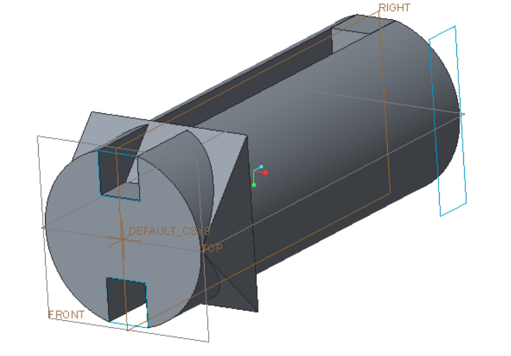
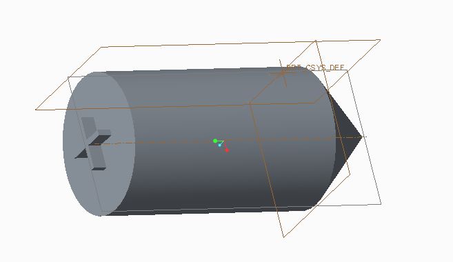
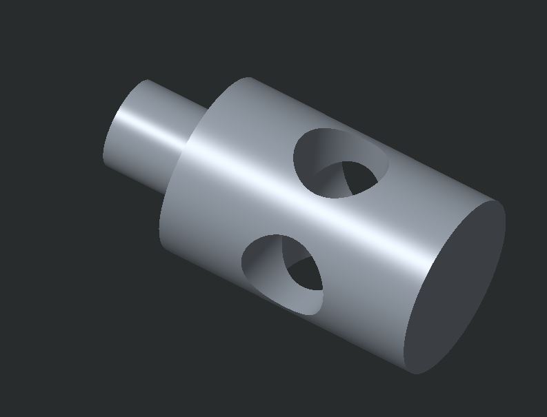
I can only print one color at a time, but I can change colors. So far 've gotten to this as a part. The plane part is easy. I'm stuck with this part because I don't know how to remove material and how to put in a second 45 degree cut. I'm working on it. I think you can get the idea of where I'm going with this. Only two parts are needed to make the model.
Nov 24, 2016
03:06 AM
- Mark as New
- Bookmark
- Subscribe
- Mute
- Subscribe to RSS Feed
- Permalink
- Notify Moderator
Nov 24, 2016
03:06 AM
Hi,
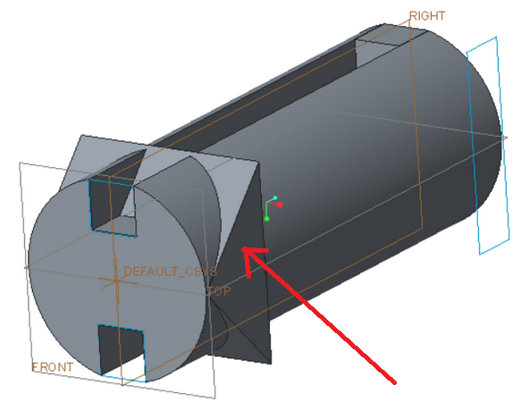
- triangular extrude adds material >>> redefine it to remove material
- during redefinition edit feature section >>> section has to enclose the area you want to remove
MH
Martin Hanák
Nov 21, 2016
01:45 PM
- Mark as New
- Bookmark
- Subscribe
- Mute
- Subscribe to RSS Feed
- Permalink
- Notify Moderator
Nov 21, 2016
01:45 PM
Hi,
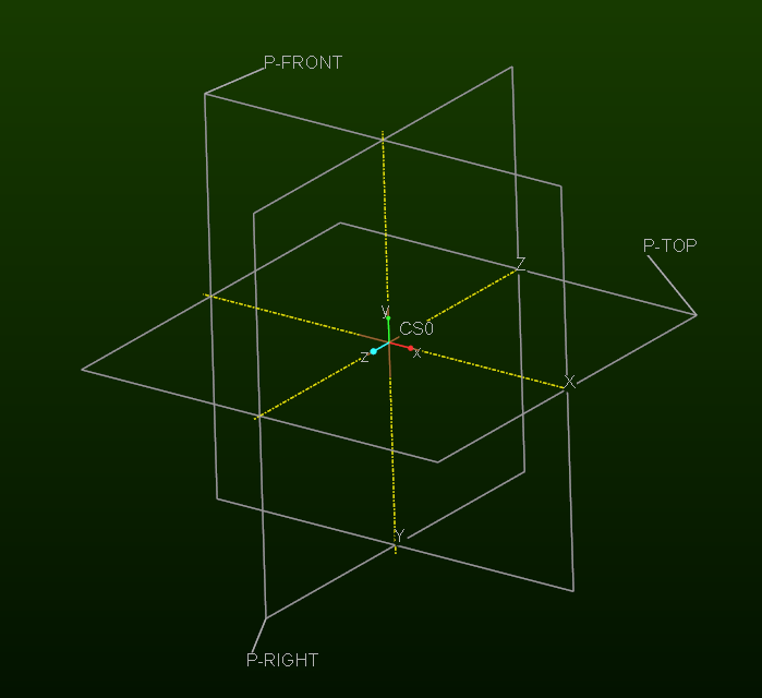
in Creo you can:
- create empty part (no features)
- create 3 default datum planes a give them requested names
- create coordinate system and orient its axes using existing datum planes as references
- save the model
Later you can use this part as template model.
MH
Martin Hanák
Nov 22, 2016
02:41 PM
- Mark as New
- Bookmark
- Subscribe
- Mute
- Subscribe to RSS Feed
- Permalink
- Notify Moderator
Nov 22, 2016
02:41 PM
You may be underestimating the intelligence level of your 5th graders. You may also want try the tri-metric default view, instead of the more common isometric view.
Bob Schwerdlin
Nov 22, 2016
02:49 PM
- Mark as New
- Bookmark
- Subscribe
- Mute
- Subscribe to RSS Feed
- Permalink
- Notify Moderator
Nov 22, 2016
02:49 PM
They certainly will not have any more difficulty than I am having.
Top-Bottom
Right-Left
Front-Back
Nov 25, 2016
09:13 AM
- Mark as New
- Bookmark
- Subscribe
- Mute
- Subscribe to RSS Feed
- Permalink
- Notify Moderator
Nov 25, 2016
09:13 AM
The way we were taught the general 3D coordinate system was to extend the 2D plane to 3D so the XY plane was the front view and the Z axis extended toward you. The 3D region of X+, Y+, and Z+ was considered to be in the same position as the 2D region of X+ and Y+ and viewed the same way with X+ to the right and Y+ to the left. This was then extended to explane rotations of the coordinate system that are commonly used in other areas. We commonly use the -XY plane as a front view.
Nov 25, 2016
12:58 PM
- Mark as New
- Bookmark
- Subscribe
- Mute
- Subscribe to RSS Feed
- Permalink
- Notify Moderator
Nov 25, 2016
12:58 PM
I think I'm on the right track;
I want make twelve gray planes labeled
Front Y-
Right X+
Top Z+
Back Y+
Left X-
Bottom Z-
six blank plane
Two red dowels labeled
+
-
Two green dowels labeled
+
-
Two blue dowels labeled
+
-
With a single color printer all of these, I should be able to make these parts (when I have a 3D printer). The planes will have 50mm x 50mm notches so they fit into the dowels. Overall dimensions of the model are 10cm X 10cm X 10cm.
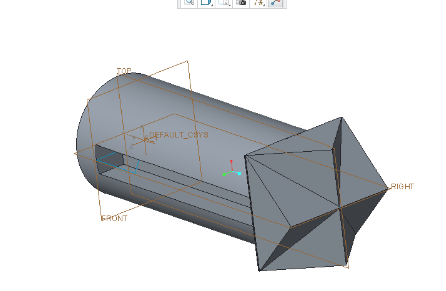
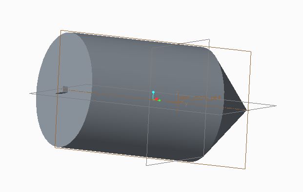
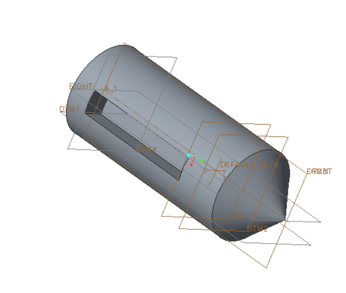
I'm stuck on the dowel problem. I can't get rid of the four unwanted protrusions so I get a pointed squarish end..
Nov 25, 2016
01:27 PM
- Mark as New
- Bookmark
- Subscribe
- Mute
- Subscribe to RSS Feed
- Permalink
- Notify Moderator
Nov 25, 2016
01:27 PM
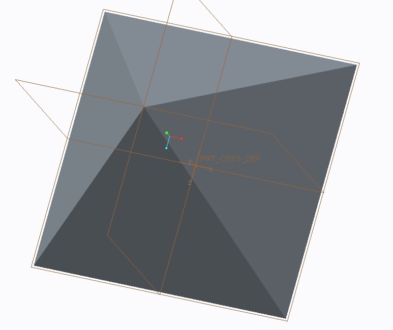
Two options come to mind if I understand the end you want to have, I'm assuming a pyramid. Create planes through the two surfaces of each triangular extrude and use solidify to remove the unwanted geometry. You could also create a blend that blends a square to a point. This is done by using two sections: 1) the square and 2) a point.
Here are images showing each option:
1) planes using solidify to remove
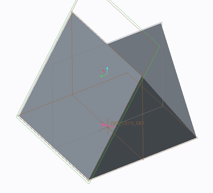
2) blend of square to point
Nov 25, 2016
06:13 PM
- Mark as New
- Bookmark
- Subscribe
- Mute
- Subscribe to RSS Feed
- Permalink
- Notify Moderator
Nov 25, 2016
06:13 PM
I use this but claim no right or wrong in it's interpretation By default, in the commercial version, that makes FRONT the X(pointing right)-Y(pointing up) plane with Z coming at you.

Nov 26, 2016
06:07 AM
- Mark as New
- Bookmark
- Subscribe
- Mute
- Subscribe to RSS Feed
- Permalink
- Notify Moderator
Nov 26, 2016
06:07 AM
Your model suggests some new designs. It lacks the XYZ indicators. This can be easily corrected. I suggest the following:
If you want a color coded system you need three parts. Then all surfaces and dowel ends must be labelled correctly.
Nov 28, 2016
10:54 AM
- Mark as New
- Bookmark
- Subscribe
- Mute
- Subscribe to RSS Feed
- Permalink
- Notify Moderator
Nov 28, 2016
10:54 AM
Antonius Dirriwachter had the best reply of all. Simple and easy to understand.
Bob Schwerdlin
Nov 28, 2016
10:55 AM
- Mark as New
- Bookmark
- Subscribe
- Mute
- Subscribe to RSS Feed
- Permalink
- Notify Moderator
Nov 28, 2016
10:55 AM
Antonius Dirriwachter had the best response of all. Simple and easy to understand.
Bob Schwerdlin
Nov 28, 2016
11:51 AM
- Mark as New
- Bookmark
- Subscribe
- Mute
- Subscribe to RSS Feed
- Permalink
- Notify Moderator
Nov 28, 2016
11:51 AM
Thanks Bob. You might look at something to clarify the difficulty understanding this process.
There are two standards that manage how you "unfold" a drawing. The version I use is 3rd angle projection.
There is also a 1st angle projection. This is a typical projection used by ISO.
Most drawings will have a small symbol on it to show how to interpret the views.
The concept is how the views fold out from the main view.
The question that you will inevitably hear is "...why is the left side of the car called right?"
My answer is "perspective"... and of course, that starts a much longer discussion.

Nov 29, 2016
09:17 AM
- Mark as New
- Bookmark
- Subscribe
- Mute
- Subscribe to RSS Feed
- Permalink
- Notify Moderator
Nov 29, 2016
09:17 AM
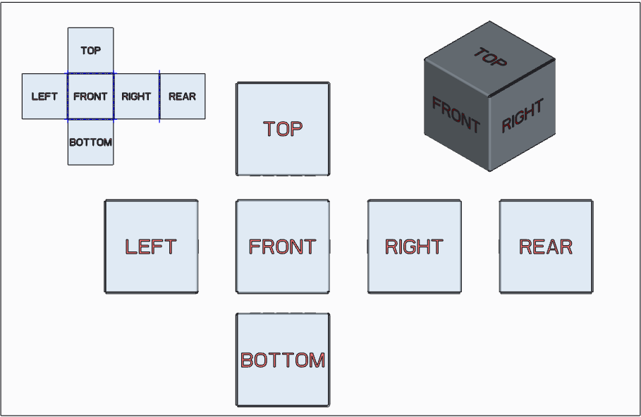
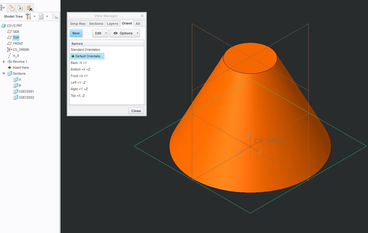
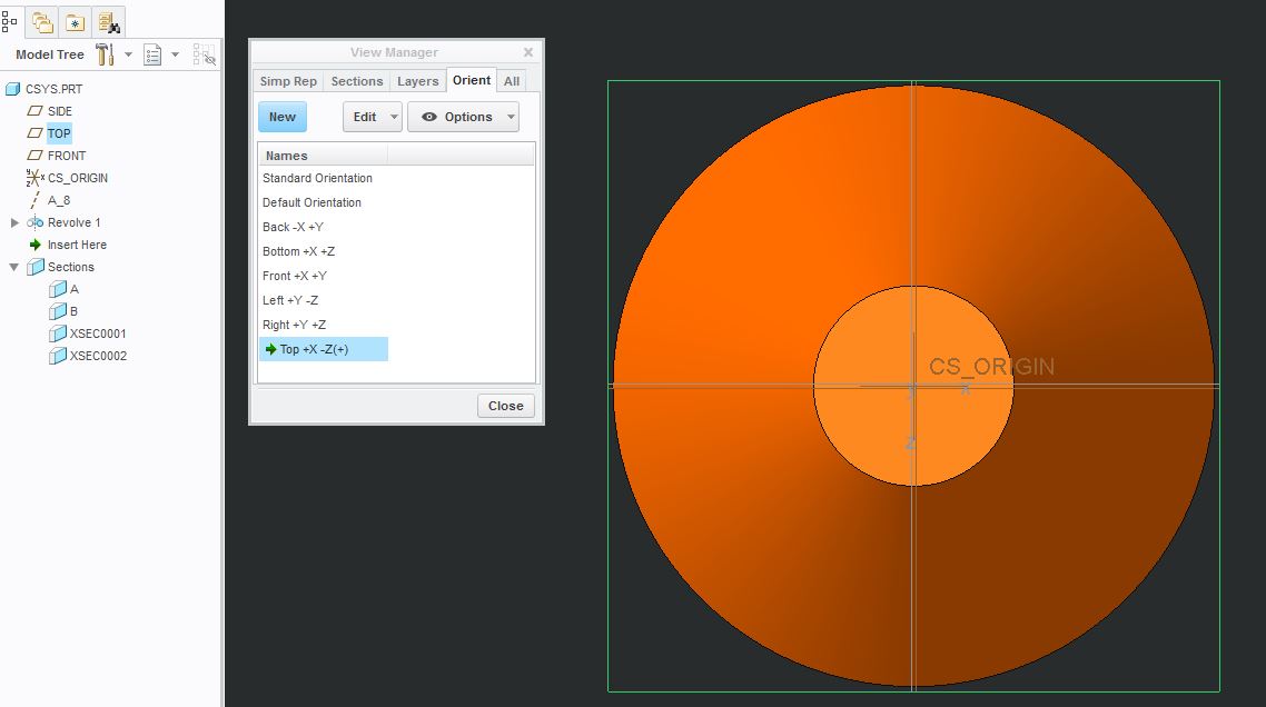
I've always looked at this simply this way:
If you are using the default planes and csys, and you orient your model to "Top", you are looking directly at the TOP plane. If you want to look at the Left or Right, you are looking at the SIDE plane. If you want to look at the front or back, you are looking at the FRONT plane.
It may help to use the View Manager to orient your views and highlight the TOP/SIDE/FRONT planes. I'm not sure if the setup at my company is out of the box, but it does list clearly which direction X/Y/Z is going (+ or -):
Nov 30, 2016
08:08 AM
- Mark as New
- Bookmark
- Subscribe
- Mute
- Subscribe to RSS Feed
- Permalink
- Notify Moderator
Nov 30, 2016
08:08 AM
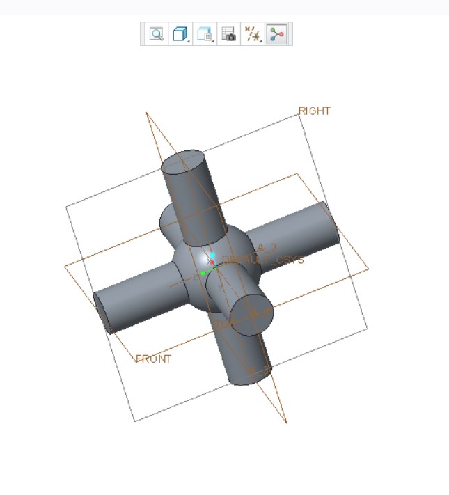
Many thanks! Your jpg's show clearly a right hand system. My focus now is to design a model students can actually make with a 3D printer (which we will get soon). The candidates are given below. The design of the center requires some thought. I can make dowels with cone points, but I haven't been able to make points which will completely fill center. I want to keep the suggested RGB = XYZ mnemonic. Dowels in Model 1 can be color coded with a single color 3D printer and PLA spools of different colors.. As you go from 3D to sketch mode 2D the process is "almost" slow enough to see what is happening.
Model 1
Alternatively,
Model 2
I still have to "square the cone."
Nov 30, 2016
09:44 AM
- Mark as New
- Bookmark
- Subscribe
- Mute
- Subscribe to RSS Feed
- Permalink
- Notify Moderator
Nov 30, 2016
09:44 AM
I'm glad the jpgs helped!
If the cones are the issue, have you considered using stepped cylinders for the axes for your block assembly design (design 1)? You could add a hole in the middle for the crossing axes to pass thru and could also step the bores in the block so it can only be assembled one way.....you'd need various sized cylinders, of course.
Your 5th graders will have a nice puzzle in the end!
Debbie
Dec 03, 2016
08:34 AM
- Mark as New
- Bookmark
- Subscribe
- Mute
- Subscribe to RSS Feed
- Permalink
- Notify Moderator
Dec 03, 2016
08:34 AM
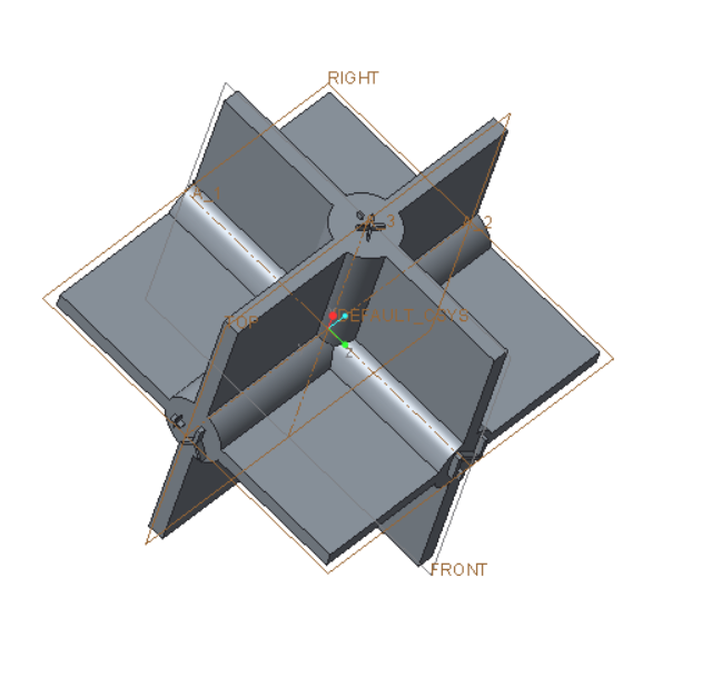
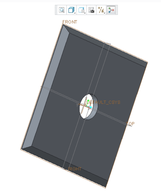
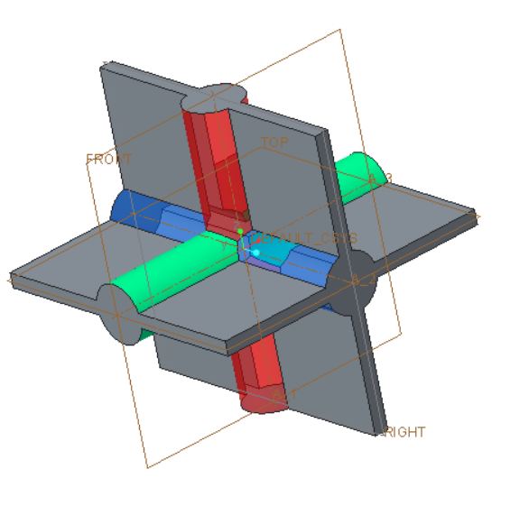
This is latest design which attempts to incorporate all suggestions. I can't call it complete until we get our 3D printer and make it. Don't worry about the PTC RGB coordinates matching the intent of the part. It's how you put the parts together that counts.
For model you need
1 center ball with six orthogonal holes - I gave up on the pyramid design and went with a cone.
6 labelled quarter planes
6 unlabeled planes
6 dowels with conical end and slots, 2 red + and -, 2 green + and -, 2 blue + and -
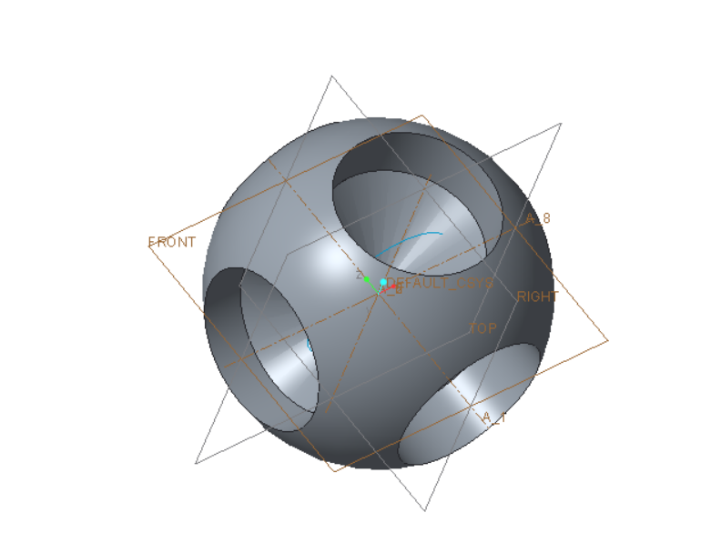
Cheers, Tom
Dec 10, 2016
12:36 AM
- Mark as New
- Bookmark
- Subscribe
- Mute
- Subscribe to RSS Feed
- Permalink
- Notify Moderator
Dec 10, 2016
12:36 AM
Looking at the Coordinates Cross-eyed.
If you look long enough at the "diamond" in the center high and low point it toggles back and forth as an optical illusion. Note, however, that only one of the alternatives is a right hand system. All PTC coordinates are right hand systems so make sure you are seeing the coordinates correctly. Note also that positive Y is on the BACK side.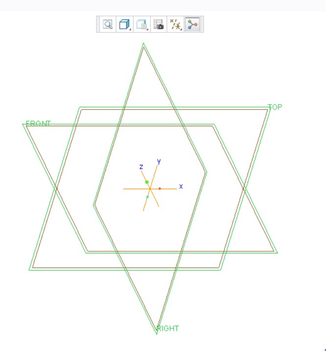
Dec 10, 2016
11:46 AM
- Mark as New
- Bookmark
- Subscribe
- Mute
- Subscribe to RSS Feed
- Permalink
- Notify Moderator
Dec 10, 2016
11:46 AM
Hi, before you finalize anything, I think you should read these discussions:
Turned around with Coordinate System
Logic behind Sketch Orientation?
Specifically, the point about avoiding naming your "default" planes as "Front", "Right", "Top"...
For example, the "usual" way to model a cube would be to start sketching by selecting Top plane; system will align the sketch such that x+ points to the right and y+ points up. You then draw a square with its lower left vertex on the origin. You would then extrude this square, let say in the +ve Z direction.
So you end up with a cube, but the next person that looks at your model would perhaps be confused because:
a) the datum plane called "Top" is on the bottom of the model?
b) the datum plane called "Right" is on the left side of the model?
Perhaps, since you have a chance to define the convention, it would be better to call the default planes "XZ" instead of "Front", "XY" instead of "Top" and "YZ" instead of "Right".
