
Turn on suggestions
Auto-suggest helps you quickly narrow down your search results by suggesting possible matches as you type.
Showing results for
Turn on suggestions
Auto-suggest helps you quickly narrow down your search results by suggesting possible matches as you type.
Showing results for
Community Tip - New to the community? Learn how to post a question and get help from PTC and industry experts! X
- Community
- Creo+ and Creo Parametric
- 3D Part & Assembly Design
- Parametric square spring?
Options
- Subscribe to RSS Feed
- Mark Topic as New
- Mark Topic as Read
- Float this Topic for Current User
- Bookmark
- Subscribe
- Mute
- Printer Friendly Page
Parametric square spring?
Aug 29, 2014
01:39 PM
- Mark as New
- Bookmark
- Subscribe
- Mute
- Subscribe to RSS Feed
- Permalink
- Notify Moderator
Aug 29, 2014
01:39 PM
Parametric square spring?
I'm trying my hand at modeling different types of parametric spring models, but I'm running into issues creating a rectangular spring. I am trying to make a parametric model of the magazine spring in a 1911 pistol (http://michigancenteroutdoors.com/sitebuildercontent/sitebuilderpictures/webassets/wolff_69162.jpg). I have succesfully created a model using a slightly tweaked version of the method shown for creating a square spring on YouTube, but the it doesn't update correctly. Here are the issues it has:
1. When the pitch parameter is changed, the trajectory for the sweep fails.
2. This method doesn't take into account that the overall width of the spring changes as it flattens out.
3. The current method requires too many steps.
If anyone out there knows of a better way to go about modeling this, I would love to hear from you. I'm attaching a copy of what I have so far for anyone that is interested in taking a look.
BTW, I am using WF4.0.
This thread is inactive and closed by the PTC Community Management Team. If you would like to provide a reply and re-open this thread, please notify the moderator and reference the thread. You may also use "Start a topic" button to ask a new question. Please be sure to include what version of the PTC product you are using so another community member knowledgeable about your version may be able to assist.
Labels:
- Labels:
-
General
18 REPLIES 18
Aug 29, 2014
03:25 PM
- Mark as New
- Bookmark
- Subscribe
- Mute
- Subscribe to RSS Feed
- Permalink
- Notify Moderator
Aug 29, 2014
03:25 PM
I think the failure for the pitch is due to DTM1 definition where the curve endpoint deviates significantly as compared to using one near the "floor" datum plane when changing pitch. Why not use the vertex of the initial extrude for the two datum planes?
I also find the sketches a bit troubling. Often times, these cannot maintain their reference when the reference moves a lot.
Overall, you can get much better transitions along the profile. A trajpar parameter can get the helical sweep closer to the extrude for a better transition; not perfect, but better.
I am also entertaining a flatten quilt to create a single loops patterned using the number of coils and pitch parameters. This requires an integer for the pitch. Also the start location will vary how you want to do this.
I don't have WF4 but it is a similar situation as Creo (did I mention I love spring challenges  )
)
One of the failures I encounter a lot is the sweep along that "intersect". When you change the number of turns by a lot, sometimes it won't select the entire length. This is really troubling for me so that is why I am thinking the patterning is useful with the one limitation of integer value of number of turns.
if you do want to use the expansion value as the spring compresses, I would recommend a "compensation factor" on the initial extrude. You could come up with a reasonable parameter by determining the angle of the end turns as they are rotating flat (pitch relation), and the overall width, same deal, use the angle to determine the change to determine the width change. More than most would put into a spring but it is manageable.
I'll see what I can do for a demo.
Aug 29, 2014
04:19 PM
- Mark as New
- Bookmark
- Subscribe
- Mute
- Subscribe to RSS Feed
- Permalink
- Notify Moderator
Aug 29, 2014
04:19 PM
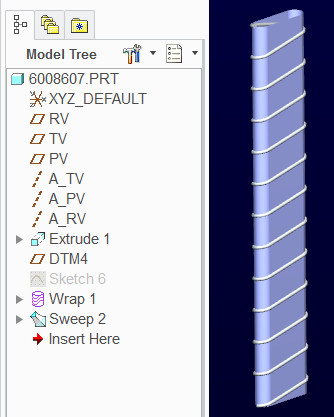
Silly me. I'm going to refer you back to a wrapped spring.
Closed and Ground Spring - Alternative to Helical Sweep
WF4 has a Wrap feature, right?
The trajpar is didn't work nicely due to the high degree of change. Looks funny.
Wrap pretty much takes care of what I was suggesting with flatten quilt.
So the only thing the Wrap needs is the overall circumference of the "barrel" multiplied by the nymber of coils, and the "barrel" needs to be the right height.
Aug 30, 2014
02:46 PM
- Mark as New
- Bookmark
- Subscribe
- Mute
- Subscribe to RSS Feed
- Permalink
- Notify Moderator
Aug 30, 2014
02:46 PM
David also has some great methods to create springs using evalgraph() in sweep sections.
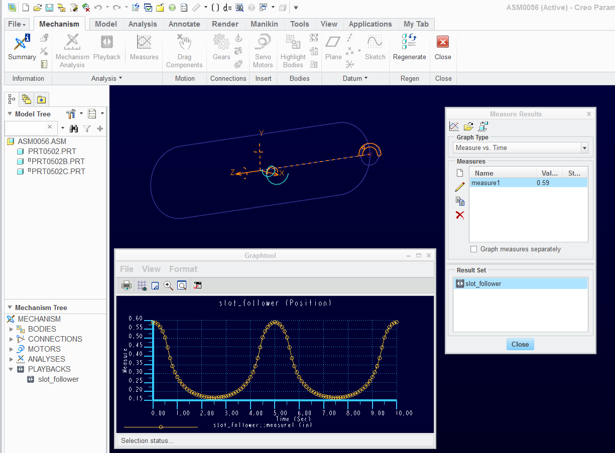
In order to capture a motion profile for a graph, you can create a mechanism analysis to give you the length through the radial sweep.
The idea is that you can capture any graph's data to Excel, and convert it to a spline. The spline -will not- have sharp edges, but for smooth transitions, this works great.
By no means is this parametric. I'm sure there is a better way to get at this, but it is -one- method for capturing a complex equation with a geometric analysis. This should be simpler but it isn't. I finally got a template to work these. But the assembly is anything but intuitive! The only hint is that it is a slot follower.
Prt1 is the path
Prt2 is an intersecting line
Prt3 is the "rabbit"... the tracer.
The assembly is a fixed path (Prt1); a pin constraint for the intersecting line (Prt2); defined as a servo motor; ramp 0 to 36 degrees x 10 seconds (default). Just a linear sweep of a line intersecting the "track".
The "rabbit" is slot-constrained to 1: the track (Prt1) using the CTRL key to select the entire periphery and apparently "any point" for axis; 2: the sweep line (Prt2) also Slot-constrained so the "rabbit" has a way to slide to and fro, and again, any point for the axis; 3; a general constraint to manage the "rabbit's" orientation and offset (1 reqd, 2 will do better).
You can test this assembly with the "dragging' the line of Prt2. The "rabbit" should follow the intersection between the "track" and the "sweeper".
Define a servo motor of the only axis in the assembly. Run the analysis making sure it is good; and save it.
Next, use the measure dialog to measure the position of the "rabbit" in relation to the CSYS. This produces a graph with x as time (we need this for the angle value in evalgraph()) and Y being the radial distance form the CSYS.
In the graph, under file, you can export the graph to Excel or a text file. the data can be formatted into a readable file for Creo when using Curve from File (-NOT- in the ribbon!) to import the data. The format is IBL. You need to get somewhat familiar with this to make the right file that can be read back into Creo.
Once you created the curve from equation, you can create a sketch and project the curve into the sketch, removing any remaining intelligence. Now save that sketch as a .sec file.
Next create a datum graph feature and use Get Data to import the section you just created. Add a CSYS and you are done (remember, this is only one full sweep). Now you have a graph that can be used for a sweep evalgraph() in a section. You can use it to determine a line length about a rotational sweep.
I know this is involved but it is a valid method for capturing specific geometry into a graph. It removes all the programming needed to come up with non-algebraic expressions. You can even mix measured analysis from Mechanism if you have a more complex profile. the point is, we have options.
Someday I will make this a two part document (creating the measurement graph and using it in evalgraph).
But for now, this is just an overview of what it takes. And if you are still reading this, you may understand this graphic.
Aug 30, 2014
03:15 PM
- Mark as New
- Bookmark
- Subscribe
- Mute
- Subscribe to RSS Feed
- Permalink
- Notify Moderator
Aug 30, 2014
03:15 PM
I have attached an .IBL file of the profile. It was manipulated in Excel by adding Z (0) and the 4 header lines. It was saved from Excel using the tab delimited file type.
Remember that the default value for X is 0 to 10. You can also change this in Excel to either be 0 to 1 or 0 to 360. A little more involved but you can do as you need. Even with a multiplier of "10", it is very workable in subsequent equations.
When you import the section data into graph, be sure to keep the 0,0 location in mind for the graph's CSYS.
Sep 01, 2014
06:45 AM
- Mark as New
- Bookmark
- Subscribe
- Mute
- Subscribe to RSS Feed
- Permalink
- Notify Moderator
Sep 01, 2014
06:45 AM
Thanks for all the input!
Sep 01, 2014
01:07 PM
- Mark as New
- Bookmark
- Subscribe
- Mute
- Subscribe to RSS Feed
- Permalink
- Notify Moderator
Sep 01, 2014
01:07 PM
Anytime
Sep 02, 2014
03:11 PM
- Mark as New
- Bookmark
- Subscribe
- Mute
- Subscribe to RSS Feed
- Permalink
- Notify Moderator
Sep 02, 2014
03:11 PM
I have no idea what I am doing wrong, but I absolutely can not get the wrap feature to work unless it is a very short curve (basically one turn of the spring). Any ideas what this could be about?
Sep 02, 2014
03:21 PM
- Mark as New
- Bookmark
- Subscribe
- Mute
- Subscribe to RSS Feed
- Permalink
- Notify Moderator
Sep 02, 2014
03:21 PM
Did you use a csys in the section/sketch feature? Is the target quilt tangent? Are the ends managed to be within or at the edge of the target? Does WF4 have a couple of options in the wrap dialog?
Sorry that I cannot provide a part that works in WF4.
Sep 02, 2014
03:34 PM
- Mark as New
- Bookmark
- Subscribe
- Mute
- Subscribe to RSS Feed
- Permalink
- Notify Moderator
Sep 02, 2014
03:34 PM
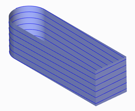
I used to use wrap to take a curve and wrap it around a rectangular block, just to see it handle the sharp corners. In that regard tangency is an unlikely problem.
It likely requires an accuracy change.
Sep 02, 2014
03:42 PM
- Mark as New
- Bookmark
- Subscribe
- Mute
- Subscribe to RSS Feed
- Permalink
- Notify Moderator
Sep 02, 2014
03:42 PM
Good to know. Haven't pushed the limits of wrap yet
Well I'll be...
Sep 02, 2014
03:38 PM
- Mark as New
- Bookmark
- Subscribe
- Mute
- Subscribe to RSS Feed
- Permalink
- Notify Moderator
Sep 02, 2014
03:38 PM
See if this has any tips you might be overlooking...
YouTube should add fast play to their enhancements.
Sep 03, 2014
07:41 AM
- Mark as New
- Bookmark
- Subscribe
- Mute
- Subscribe to RSS Feed
- Permalink
- Notify Moderator
Sep 03, 2014
07:41 AM
Finally got the wrap feature to work and it was because I was using the wrong CSYS. I didn't realize that there was a sketcher CSYS. Thanks again!
Sep 03, 2014
11:31 AM
- Mark as New
- Bookmark
- Subscribe
- Mute
- Subscribe to RSS Feed
- Permalink
- Notify Moderator
Sep 03, 2014
11:31 AM
Yea, that get a lot of people.
Enjoy!
Sep 04, 2014
04:28 AM
- Mark as New
- Bookmark
- Subscribe
- Mute
- Subscribe to RSS Feed
- Permalink
- Notify Moderator
Sep 04, 2014
04:28 AM
Did you consider using an elipical helix instead of a cylindical one? I just downloaded your model to have a look & wondered what would happen if you intersected an elipical helix with your base feature. I think it gave a better result. The elipical helix was created by equation.
Regards
John
Sep 04, 2014
11:30 AM
- Mark as New
- Bookmark
- Subscribe
- Mute
- Subscribe to RSS Feed
- Permalink
- Notify Moderator
Sep 04, 2014
11:30 AM
What equation did you use, John?
Sep 05, 2014
02:38 AM
- Mark as New
- Bookmark
- Subscribe
- Mute
- Subscribe to RSS Feed
- Permalink
- Notify Moderator
Sep 05, 2014
02:38 AM
Hi Antonius, i used the following equation.
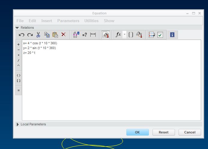
Regards
John
Sep 05, 2014
05:38 PM
- Mark as New
- Bookmark
- Subscribe
- Mute
- Subscribe to RSS Feed
- Permalink
- Notify Moderator
Sep 05, 2014
05:38 PM
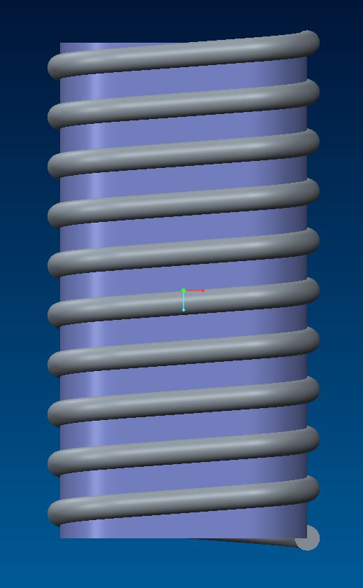
Thanks John. That is pretty darn close to flat along the straight run.
I wasn't able to get anything close to this using a cylindrical formula.
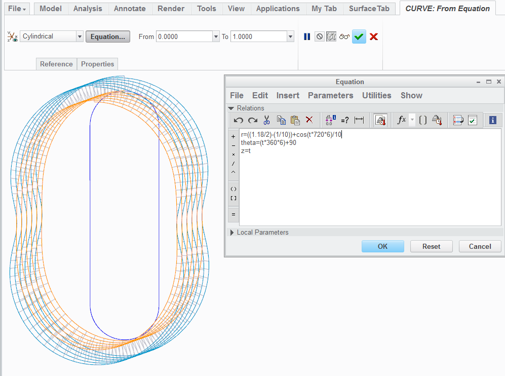
I can come close if the ratio is 2:3 using cylindrical equations.
Here is a close approximation of an obround...
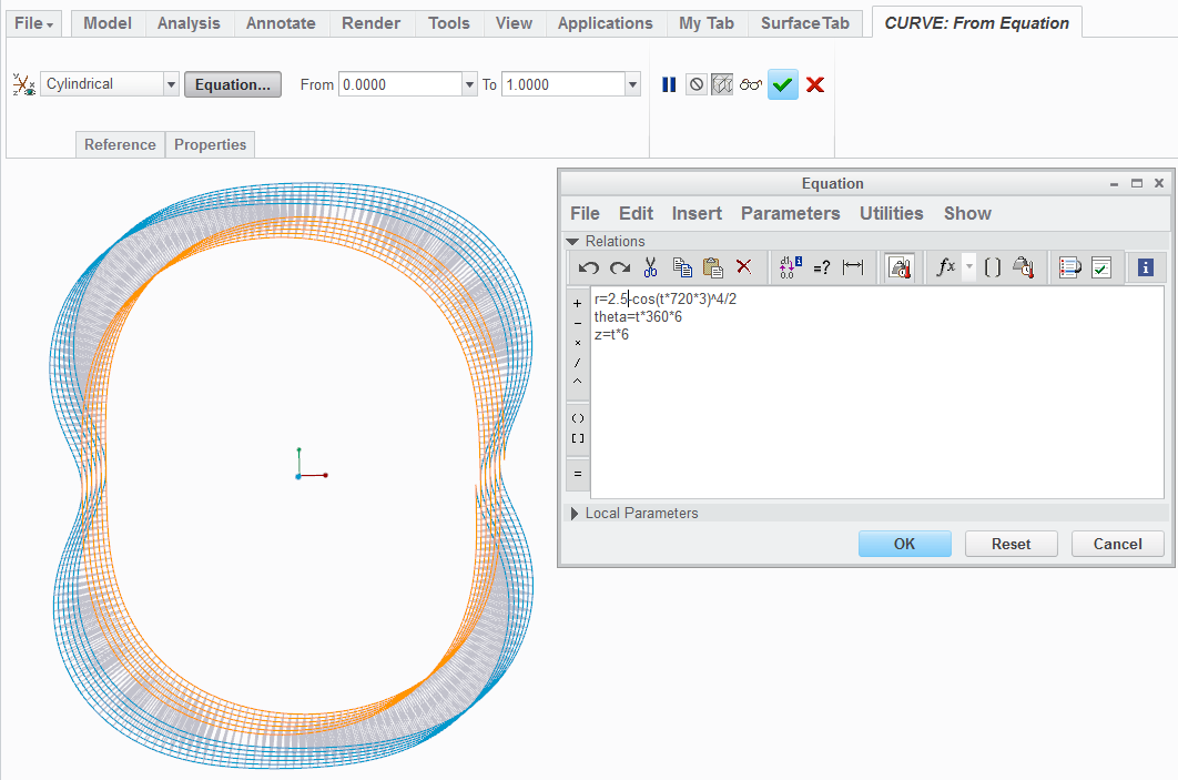
And I like this one because it has that slightly "squashed/heft" look to it...
Sep 04, 2014
05:48 PM
- Mark as New
- Bookmark
- Subscribe
- Mute
- Subscribe to RSS Feed
- Permalink
- Notify Moderator
Sep 04, 2014
05:48 PM
With all this talk, I looked back in my old files as I remember doing a wrap and comparing the results if an intersected curve and a wrapped one. This is from 2001:
When I did a spinal bend on it, it simply moved the "S" distortion to the short sides.
Now, what if I........ 
