
Turn on suggestions
Auto-suggest helps you quickly narrow down your search results by suggesting possible matches as you type.
Showing results for
Turn on suggestions
Auto-suggest helps you quickly narrow down your search results by suggesting possible matches as you type.
Showing results for
Community Tip - Your Friends List is a way to easily have access to the community members that you interact with the most! X
- Community
- Creo+ and Creo Parametric
- 3D Part & Assembly Design
- Positioning an imported sketch
Options
- Subscribe to RSS Feed
- Mark Topic as New
- Mark Topic as Read
- Float this Topic for Current User
- Bookmark
- Subscribe
- Mute
- Printer Friendly Page
Positioning an imported sketch
Jan 14, 2014
10:34 AM
- Mark as New
- Bookmark
- Subscribe
- Mute
- Subscribe to RSS Feed
- Permalink
- Notify Moderator
Jan 14, 2014
10:34 AM
Positioning an imported sketch
Hello all, when I import a sketch from file (an autocad drawing), in sketcher, when I try to position the sketch it always changes. For instance, I have a sketch that I want to position coincident with an existing line, but when I choose the sketch line and make it coincident, instead of moving the entire sketch and keeping all the existing dimensions and contraints from the autocad file, it moves just the line to be coincident and the rest of the sketch is all messed up. The only way I have found to position an imported sketch after import is to manually constrain every single line or point so that they can't move when I try to move the whole sketch. This is such a pain. does anyone know a better way? Thanks in advance!
This thread is inactive and closed by the PTC Community Management Team. If you would like to provide a reply and re-open this thread, please notify the moderator and reference the thread. You may also use "Start a topic" button to ask a new question. Please be sure to include what version of the PTC product you are using so another community member knowledgeable about your version may be able to assist.
Labels:
- Labels:
-
General
12 REPLIES 12
Jan 14, 2014
10:52 AM
- Mark as New
- Bookmark
- Subscribe
- Mute
- Subscribe to RSS Feed
- Permalink
- Notify Moderator
Jan 14, 2014
10:52 AM
Not sure what you are trying to acomplish. I use Acad drawings quite often to model old tooling/fixtures into pro/e. I create a part called xxx_acad.prt. Insert shared data. this is now viewable in sketcher and will not change. You can choose referance to constrain the sketched lins to. Once my model is complete I remove all constraints from the acad data which can be suppressed or deleted as you see fit.
Good Luck
Jan 14, 2014
10:57 AM
- Mark as New
- Bookmark
- Subscribe
- Mute
- Subscribe to RSS Feed
- Permalink
- Notify Moderator
Jan 14, 2014
10:57 AM
I am trying to position the sketch in relation to existing geometry on the part. For instance, I am trying to make an extruded cut on this part, so I need the imported autocad sketch to line up with my existing part. But when I choose the existing line of the part as a reference that I want the sketch coincident with, and choose to make those two lines coincident, instead of moving the whole sketch, it just moves that one line and makes it coincident, and the rest of the sketch stays put, making all the dimensions wrong. Not sure if I'm explaining it where you can understand or not. If there was a to choose references when you initially place the sketch, where it asks for the angle and scale, that would be awesome, because on that screen the sketch moves as one piece. But it won't allow to me to choose references to position the sketch there, at least not that I have found.
Jan 14, 2014
10:56 AM
- Mark as New
- Bookmark
- Subscribe
- Mute
- Subscribe to RSS Feed
- Permalink
- Notify Moderator
Jan 14, 2014
10:56 AM
It depends.
If it's going to be parametric, then import it into a sketch directly; not as the basis for a feature, but as New-->Sketch. Dimension the pieces as you like and save this sketch (*.sec) You can the place that .sec and it will behave better. I find it advantageous to include a vertical and horizontal centerline in the sketch so that all the dimensions in the sketch can trace back to those. When the sketch is placed, the centerlines can be aligned or dimensioned and the rest of the sketch will follow.
If it is not necessary to be parametric, then I import it as a datum curve relative to a CSYS. This eliminates the need to dimension anything except the CSYS. You can build features from the datum curve with use edge, offset edge, or just as dimensioning references.
Jan 14, 2014
11:04 AM
- Mark as New
- Bookmark
- Subscribe
- Mute
- Subscribe to RSS Feed
- Permalink
- Notify Moderator
Jan 14, 2014
11:04 AM
For instance, here is a screen shot of what I'm trying to do. I have my sketch imported, exactly the dimensions I want. All I want to do now is make the top line of the sketch coincident with the top line of my existing extrustion (the dashed datum). But if I select to make those lines coincident, instead of rotating my whole sketch and keeping all those dimensions, it will move that top line to be coincident and leave everything else where it is now, messing up all the dimensions.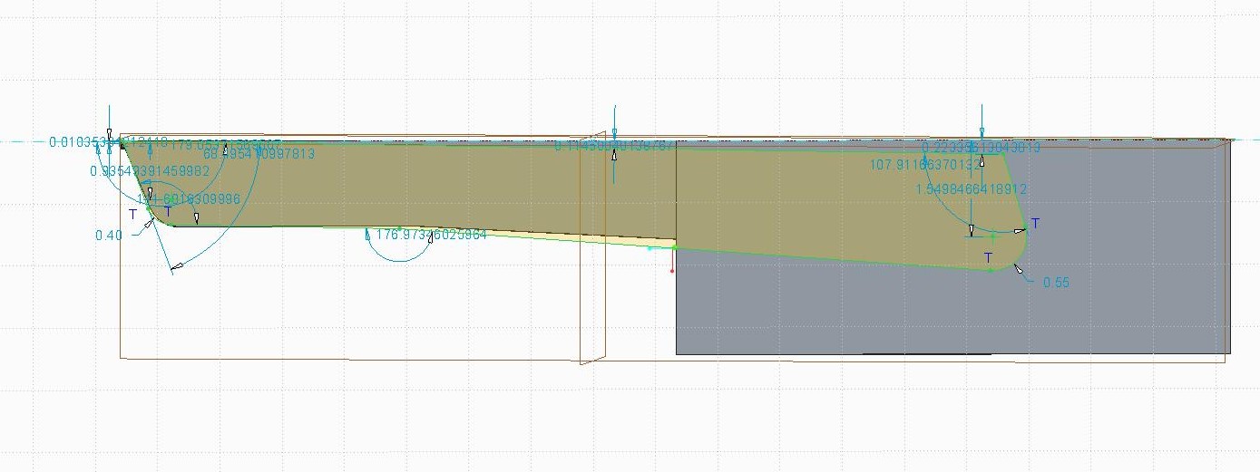
Jan 14, 2014
11:12 AM
- Mark as New
- Bookmark
- Subscribe
- Mute
- Subscribe to RSS Feed
- Permalink
- Notify Moderator
Jan 14, 2014
11:12 AM
You can lock the dimensions you like. Lock is available when you have one or more dimensions selected and you right click to get a menu.
Jan 14, 2014
11:21 AM
- Mark as New
- Bookmark
- Subscribe
- Mute
- Subscribe to RSS Feed
- Permalink
- Notify Moderator
Jan 14, 2014
11:21 AM
That does work for the selected dimensions, but in this case even when I select all the shown dimensions and lock them, when I use the coincident constraint, it keeps the selected shown dimensions locked and completely distorts other parts of the sketch that weren't locked. I have also tried selecting the whole sketch and locking it but that doesn't work either. There are always critical dimensions apparently that aren't shown, so they don't get locked. I've tried figuring out what dimensions I need to be locked and making sure I manually dimension them but it never seems to work, there is always some area of the sketch that didn't get locked when I try to move it.
Jan 14, 2014
11:31 AM
- Mark as New
- Bookmark
- Subscribe
- Mute
- Subscribe to RSS Feed
- Permalink
- Notify Moderator
Jan 14, 2014
11:31 AM
Try the previous suggestion - either create a New Sketch and save the section or import it as a datum curve.
It seems like the sketch is not well constrained. If you create a New Sketch, make sure the weak dimensions are visible so you can see what's not constrained. sketcher_disp_weak_dimensions should be Yes.
If you import it as a datum curve the section cannot distort
Jan 14, 2014
01:04 PM
- Mark as New
- Bookmark
- Subscribe
- Mute
- Subscribe to RSS Feed
- Permalink
- Notify Moderator
Jan 14, 2014
01:04 PM
I will try this method as well, thanks for your help!!
Jan 14, 2014
12:09 PM
- Mark as New
- Bookmark
- Subscribe
- Mute
- Subscribe to RSS Feed
- Permalink
- Notify Moderator
Jan 14, 2014
12:09 PM
Here's my methodology for importing ACAD files that I don't want to change after import:
- Determine an origin for the imported geometry. For example, if it's a logo, I might want it to be the center of the logo.
- Create a coordinate system at that origin in the Creo part.
- Edit the ACAD file and move the ACAD geometry so it is positioned properly relative the origin (0,0).
- import the ACAD file as a curve. In WF that's Inset > Shared Data > From File, in Creo expand the Get Data section of the Model tab and pick Import.
- Select the coordinate system you created to place the import.
You now have a curve in your model to use for other sketches or features, properly positioned and scaled.
Jan 14, 2014
12:22 PM
- Mark as New
- Bookmark
- Subscribe
- Mute
- Subscribe to RSS Feed
- Permalink
- Notify Moderator
Jan 14, 2014
12:22 PM
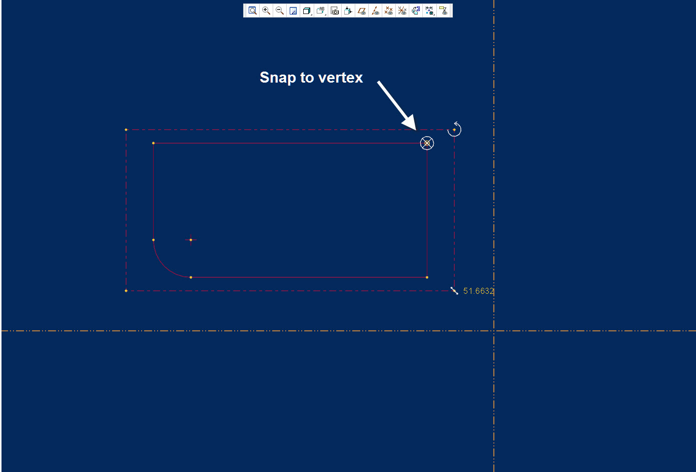
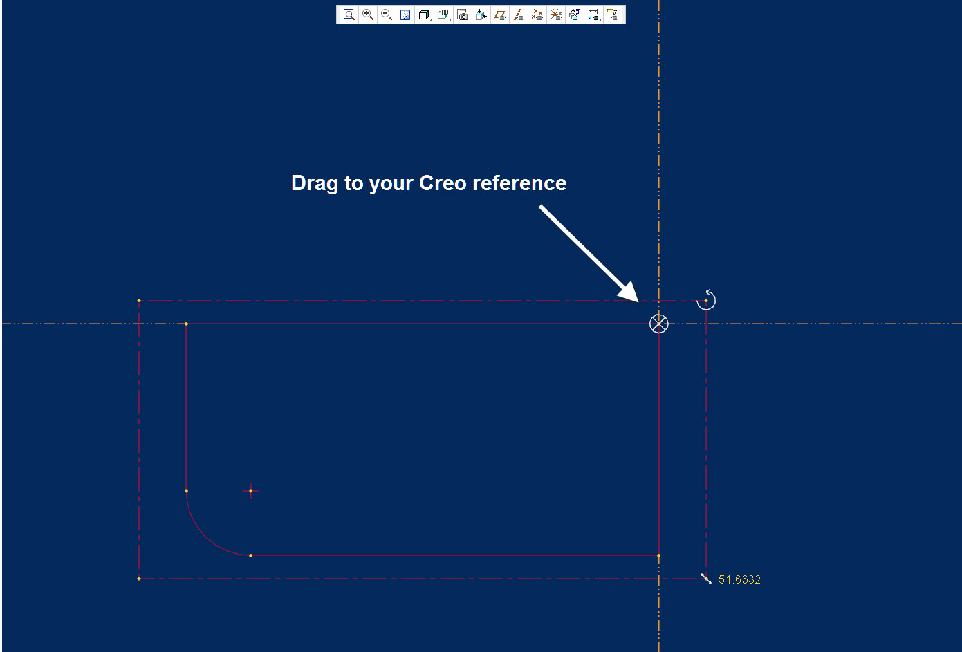
Whenever i import a sketch, whether it be from my sketcher palette or from AutoCAD, I reposition the sketch prior to finally placing it. If you right click and hold on the "X" dragger, you can move it to anywhere on the sketch you like and it will snap to vertices or edges. Then use your a left click to drag the whole sketch to the desired reference.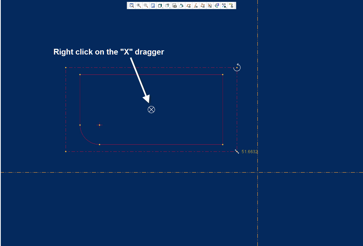
Jan 14, 2014
12:37 PM
- Mark as New
- Bookmark
- Subscribe
- Mute
- Subscribe to RSS Feed
- Permalink
- Notify Moderator
Jan 14, 2014
12:37 PM
Oh wow, this is what I was looking for. I had no idea you could move that X thing. Now my only problem is fixing the rotation of the sketch, I see how I can rotate it if I know the angle, but I need to rotate it to be coincident with my existing line. This is so helpful though.
Jan 14, 2014
03:06 PM
- Mark as New
- Bookmark
- Subscribe
- Mute
- Subscribe to RSS Feed
- Permalink
- Notify Moderator
Jan 14, 2014
03:06 PM
Since the sketcher's solver wants to apply horizontal and vertical constraints, you might begin with having the reference planes oriented the way you want the sketch oriented. This means you want a different normal plane to determine horizontal or vertical when defining the sketch planes.
This is not required, but does make it easier.
